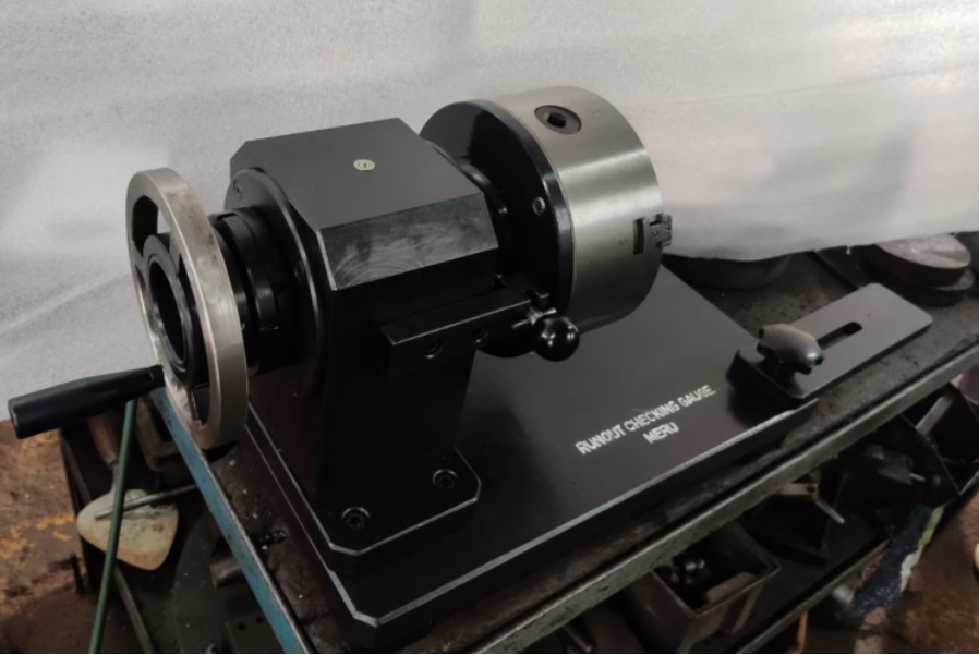
Tool runout is the amount a rotating tool or spindle moves away from its intended axis. Measure total indicated runout with a dial indicator, check the full toolholding assembly, and correct dirt, damage, poor alignment, or worn parts before machining.
In U.S. machine shops, tool runout can affect everything from a small drill hole to a large CNC milling job. A cutter may look straight while sitting still but move off-center as the spindle turns. This movement can cause uneven cuts, poor surface finish, excess noise, and early tool wear. The best way to check it is to measure the rotating assembly against a known reference.
Tool runout and rotational accuracy are closely linked, but they are not the same thing as balance. Runout describes the change in position of a surface during rotation. Rotational accuracy describes how closely the full spindle and tool system follows its intended axis. A clean taper, sound holder, correct collet, straight tool shank, and healthy spindle all help control this error. This guide explains how to find the source, measure the error, read the result, and choose a suitable correction without guessing at a universal tolerance.
Source: en.nc-net.com
What Is Tool Runout and Why Does It Matter?
Tool runout is the difference between the position of a rotating surface and its intended rotational axis. In simple terms, the tool does not follow one exact center line. Instead, its measured surface moves slightly as it turns. This movement is often called wobble, although runout gives a more useful way to describe and measure it.
Machinists commonly use total indicated runout, or TIR, to report this error. A dial indicator touches the rotating surface and records the highest and lowest readings during one full turn. The difference between those readings is the TIR value. A lower reading usually means the measured surface runs closer to the intended axis.
For example, imagine that an indicator shows a high reading of 0.012 mm and a low reading of -0.006 mm. The TIR is 0.018 mm. The calculation is simple: 0.012 minus -0.006 equals 0.018 mm. The result describes the full indicator movement, not just the distance from the center.
Source: meruprecisionindustries.com
Runout
The measured variation of a rotating surface relative to a specified reference axis.
Total Indicated Runout
The difference between the maximum and minimum indicator readings during a complete rotation.
Rotational accuracy
The ability of a spindle and its connected parts to rotate close to their intended axis with controlled geometric and motion errors.
Wobble
A common visual description of uneven movement. It may come from radial runout, angular error, axial movement, or another mechanical problem.
How Total Indicated Runout Works
A dial indicator turns small changes in position into a visible needle movement. When the measured surface rotates, the needle moves between its highest and lowest points. The difference gives the total indicated runout at that measurement location.
TIR is not always the same as the actual offset of the rotational axis. A measured result can include surface shape errors, mounting errors, centering errors, and spindle motion. For a perfectly round surface with pure eccentricity, the indicated runout may be twice the radial offset. However, real assemblies can contain several error sources. Do not divide a TIR result by two unless the applicable measurement method calls for it.
Why the Measurement Location Matters
Runout can change along the length of a tool or test bar. A small angular error near the spindle can produce a larger movement farther from the mounting point. This is why one measurement near the holder does not always describe the movement at the cutting end.
A useful inspection records the exact measurement position. It may include the spindle nose, holder gauge line, exposed shank, and a point farther along a test bar. Comparing these readings helps show whether the problem comes from a simple offset or an angular alignment error.
Types of Tool Runout and Rotational Error
Tool runout can appear in more than one direction. The correct measurement depends on which surface moves, where the error occurs, and how the tool is held. Knowing the difference helps prevent a machinist from treating every wobble as the same fault.
A useful first step is to separate radial, axial, and angular runout. It is also helpful to separate static geometric runout from dynamic spindle behavior. Each type points toward a different inspection method and may need a different repair.
Source: youtube.com
Radial runout
Movement across the rotational axis. The indicator touches a cylindrical surface, with its measuring direction set across the axis.
Axial runout
Movement along the rotational axis. It is commonly checked on a spindle face or another suitable end surface.
Angular runout
A condition where the tool axis is tilted relative to the spindle axis. The measured movement can increase farther from the mounting point.
Dynamic error
Additional movement or vibration that appears during operation because of speed, bearings, imbalance, resonance, or other running conditions.
Radial Runout
Radial runout is one of the most common concerns in drilling, milling, routing, and grinding. The tool moves away from the intended center line as the spindle rotates. A dial indicator placed against a suitable cylindrical surface records this side-to-side change.
This error can affect the actual cutting diameter. For example, a drill with poor radial accuracy may produce a hole larger than its nominal size. An end mill may also load its cutting edges unevenly. The final result depends on tool design, workpiece material, cutting conditions, and the amount of runout.
Axial Runout
Axial runout occurs when a face or other suitable end surface moves along the spindle axis during rotation. It can affect face milling, surface contact, and operations where the position of the cutting edges matters.
A dial indicator checks this movement by touching the selected face with its measuring direction parallel to the rotational axis. The measurement position matters because a face may show different readings at different radii. Always follow the specified test method.
Angular Runout and Tool Tilt
Angular runout occurs when the tool axis is not parallel to the intended spindle axis. The tool may appear close to the center near the holder but move farther away as the distance increases. This can create uneven cutting conditions along the tool.
A practical way to investigate this problem is to compare readings at two known positions on a suitable test bar. A growing reading farther from the spindle can indicate angular error. However, the result may also include bar straightness and other measurement errors, so the setup must be checked before drawing a conclusion.
Static Runout, Dynamic Runout, and Balance
Static runout is checked while the spindle is stopped and the assembly is turned slowly by an approved manual method. It mainly reveals geometric and mounting errors in the parts being measured. This test is useful because it can be performed without running the spindle at working speed.
Dynamic behavior includes errors that appear or change while the spindle operates. Worn bearings, loose parts, vibration, thermal changes, and spindle resonance may affect the result. A static indicator reading alone cannot describe every dynamic condition.
Runout and balance are also different. Runout is a geometric measurement, while imbalance relates to uneven mass distribution around the rotational axis. A tool can have low measured runout but still cause strong vibration because it is poorly balanced. Both conditions deserve separate checks when high-speed operation is involved.
How Tool Runout Affects Machining Accuracy
Excessive runout changes how a cutting tool meets the workpiece. Instead of sharing the cutting load evenly, one edge may remove more material than another. This creates uneven force, heat, and wear. The effect can grow during long cuts or when using small precision tools.
The problem is not limited to the cutting edge. Runout can also affect hole size, surface location, tool life, vibration, and the repeatability of finished parts. The amount of damage depends on the machining process and the tolerance required.
Source: en.nc-net.com
Uneven cutting loads
Some flutes may take a larger chip than others, causing uneven force and early wear.
Poor surface finish
Unequal cutting action can leave marks, uneven surfaces, and unwanted texture.
Incorrect hole size
Drills and other rotary tools may produce holes larger than expected or with poor geometric quality.
Shorter tool life
An overloaded cutting edge may wear, chip, or fail before the other edges reach the same condition.
Vibration and noise
Uneven forces can contribute to vibration, unstable cutting, and unwanted machine noise.
Poor repeatability
Changes in tool seating or rotational position can create variation between parts and machining cycles.
Why Small Tools Need Careful Runout Control
Small tools are often more sensitive to the same absolute runout value. A 0.01 mm error represents 0.5 percent of a 2 mm tool diameter. The same error represents only 0.05 percent of a 20 mm diameter.
This comparison does not create a universal tolerance, but it shows why a small end mill or micro drill may need much closer control. A small amount of movement can take up a meaningful share of the available cutting geometry. Precision work therefore needs a measurement limit that matches the tool size and the required result.
Effects on Milling, Drilling, and Grinding
During milling, runout can cause one flute to carry more load than the others. This may produce uneven wear and surface marks. The problem can become more noticeable when the tool has several cutting edges or a long overhang.
During drilling, a tool that does not rotate true may cut outside its intended path. Hole size and roundness can suffer, especially when the setup is already weak or the workpiece is difficult to machine.
During grinding, spindle and wheel mounting accuracy affect contact and surface quality. Wheel runout can create uneven grinding action. The wheel, flange, spindle, and dressing condition must all be checked under the correct safety procedure.
The Link Between Runout and Tool Life
A cutting edge that carries too much load may become hot and wear faster. It may also chip when the material or cutting condition changes. The remaining edges then work under a different load, which can make the cut less stable.
Reducing runout can help balance the cutting action, but it does not solve every tool-life problem. Incorrect feed, speed, tool geometry, poor workholding, and unsuitable coolant can also cause early failure. Check the full cutting process before changing only one setting.
Common Causes of Tool Runout and Wobble
Tool runout often comes from several small errors within the same assembly. A spindle may be accurate, but a dirty holder or damaged collet can still make the cutting tool run off-center. The opposite can also happen: a good holder may reveal a problem in the spindle itself.
For this reason, it is better to inspect the assembly in stages instead of replacing parts at random. Start with the surfaces that are easy to clean and check. Then move toward the spindle and its internal components if the reading remains high.
Source: meruprecisionindustries.com
Dirty spindle taper
Chips, dust, or dried residue can prevent the holder from seating correctly and create a measurable offset.
Damaged toolholder
Scratches, dents, wear, or poor manufacturing accuracy can affect the way the holder fits into the spindle.
Worn or incorrect collet
A damaged collet or one outside its approved gripping range may not hold the tool centrally.
Bent tool shank
A bent or poorly finished shank may create runout even when the holder and spindle are in good condition.
Incorrect assembly
Poor seating, wrong components, uneven tightening, or incorrect torque can affect the final tool position.
Spindle bearing wear
Damaged or worn bearings may cause excessive movement, vibration, and poor rotational accuracy.
Excessive tool overhang
A long tool extension can increase the movement measured near the cutting end and may also increase deflection during cutting.
Contamination Between Mating Surfaces
A small chip trapped between two precision surfaces can change the way a toolholder sits. The holder may not contact the spindle taper evenly. This can create runout even when neither component has a major visible defect.
Clean the spindle nose, holder taper, collet, nut, and tool shank with suitable lint-free materials. Inspect each surface under good light. Follow the machine and holder manufacturer’s cleaning instructions, because the correct surface condition and lubrication requirements can vary by system.
Collet and Toolholding Problems
A collet must match the tool shank and the holder system. Using the wrong size or gripping outside the approved range can reduce clamping accuracy. A damaged collet may also close unevenly around the tool.
Check the collet slots, contact surfaces, nut, and holder bore. Replace parts that show cracks, deformation, or excessive wear. Do not try to correct a damaged precision component by forcing it into position.
Spindle and Bearing Problems
A worn spindle bearing can cause movement that is not explained by a simple toolholder problem. The machine may also show unusual heat, vibration, noise, or changes in accuracy as speed increases.
If a known-good test bar still shows excessive movement after the mounting surfaces are clean, follow the machine manufacturer’s spindle inspection procedure. Bearing adjustment, spindle repair, and internal alignment work should be handled by qualified service personnel.
Excessive Tool Stickout
Tool stickout is the length of the tool that extends beyond its holding point. A longer extension can make angular errors more visible at the end of the tool. It can also increase bending under cutting force.
Use the shortest extension that allows safe access to the workpiece. Keep enough clearance for the holder, spindle, and workholding system. Do not shorten the tool so much that the holder collides with the workpiece or fixture.
How to Measure Tool Runout With a Dial Indicator
A dial indicator or dial test indicator provides a practical way to measure tool runout. The method is simple, but the result depends on a stable setup, a suitable measuring surface, and a clear reference. A precision test bar is often better than a cutting edge because it provides a smooth surface for the indicator.
Before starting, check the machine manual and the toolholder manufacturer’s procedure. The following method describes a general manual inspection. It does not replace a machine-specific service test or a qualified spindle inspection.
Source: youtube.com
Required tools
Use a suitable dial indicator, a rigid magnetic base or approved fixture, a precision test bar, clean lint-free cloths, and the correct machine documentation.
Safe machine condition
Stop the spindle and place the machine in the required safe state. Apply the shop’s lockout procedure when required. Never place hands or an indicator near a powered rotating spindle.
Suitable measuring surface
Choose a clean, smooth cylindrical surface or a specified face. Avoid keyways, damaged areas, rough cutting edges, and surfaces that cannot give a stable reading.
Step 1: Prepare the Spindle and Toolholder
Stop the machine and secure it according to the manufacturer’s instructions. Remove chips and loose material from the work area. Confirm that the spindle cannot start unexpectedly while the measurement is being set up.
Inspect the spindle taper, holder, collet, and test bar. Clean the contact surfaces with suitable materials. Look for dents, scratches, rust, and signs of wear. Replace damaged parts before using them for an accuracy check.
Step 2: Install a Suitable Test Bar
Fit a precision test bar that matches the spindle and toolholding system. Seat it correctly and follow the specified clamping procedure. Make sure that the bar is not bent, damaged, or contaminated.
If you want to measure the complete cutting assembly, you can also inspect a suitable tool shank after checking the test bar. Keep the two results separate. A test bar reading checks the spindle and mounting arrangement, while a tool reading includes the tool itself.
Step 3: Set Up the Dial Indicator
Attach the indicator to a rigid part of the machine or an approved fixture. The base must not move during the test. Position the contact point against the cylindrical surface so that it measures in the radial direction.
Apply a suitable amount of indicator preload without exceeding the instrument’s travel range. Make sure the contact point stays on the surface throughout the rotation. Check that the stand, arm, and base are secure before taking readings.
Step 4: Rotate the Assembly Slowly
Use only the machine manufacturer’s approved manual rotation method. Turn the assembly through one complete revolution without applying side pressure. Watch the indicator and identify the highest and lowest readings.
Record both values and calculate TIR by subtracting the lowest reading from the highest. Repeat the measurement to check consistency. If the readings change greatly between attempts, inspect the indicator stand, contact angle, surface condition, and mounting setup.
Step 5: Measure at More Than One Position
Take another radial measurement farther along the test bar when the procedure allows it. Use a known distance and record the position. A larger reading farther from the holder may point toward angular error, although the straightness of the test bar must also be considered.
If axial runout is part of the inspection, place the indicator against the specified spindle face or suitable end surface. Set its measuring direction parallel to the spindle axis. Rotate the assembly slowly and record the full indicator movement.
Step 6: Record the Result
A useful inspection record includes the machine identification, spindle type, holder type, test bar, indicator resolution, measurement position, spindle condition, and TIR result. Also record whether the assembly was cold or had reached its normal operating temperature.
Use the same setup for later checks whenever possible. This makes it easier to compare results over time. A single reading can show a problem, but repeatable measurements are more useful for maintenance decisions.
Signs of a Good Measurement
A reliable test has a rigid indicator base, a clean measuring surface, a suitable contact angle, and a repeatable result. The contact point remains on the surface throughout the turn. The reading does not change because the indicator stand moves or the operator pushes on the assembly.
If the reading jumps, sticks, or changes with hand pressure, stop and correct the setup. Do not accept an unstable reading simply because it falls within a desired tolerance.
Acceptable Runout, Troubleshooting, and Improving Rotational Accuracy
An acceptable runout value depends on the machine, spindle, toolholder, cutter, tool diameter, and required part accuracy. A general-purpose drilling operation may allow more movement than a precision finishing cut. Small tools and high-speed operations often need tighter control.
Do not use one online number as the limit for every setup. Check the machine service manual, toolholder specifications, cutting tool documentation, and engineering drawing. These sources define the conditions that apply to the actual equipment and job.
Source: en.nc-net.com
Check the manufacturer’s limit
Use the exact spindle, test bar, measurement position, and method stated in the service documentation.
Compare like with like
Do not compare a spindle taper reading with a tool-tip reading or measurements taken at different distances.
Inspect before replacing parts
Clean and check the assembly first, then isolate the spindle, holder, collet, and tool.
Investigate changes over time
A rising runout value may show wear, damage, contamination, or a change in the mounting condition.
Why There Is No Universal Runout Limit
A runout limit is meaningful only when its measurement conditions are known. A spindle manufacturer may specify one limit at the taper and another at a point farther along a test bar. These values are not interchangeable.
For example, Haas publishes VMC spindle taper maintenance guidance with model-specific checks. Its stated limits include 0.0002 in (0.005 mm) at the spindle taper, 0.0005 in (0.013 mm) at the test bar gauge line, and 0.001 in (0.025 mm) at a point 6 in (150 mm) below the gauge line. These are examples for the stated Haas procedure, not universal limits for all CNC machines.
The example also shows why the measurement distance matters. A result farther from the spindle may be higher because angular error and other geometric effects become more visible. Always use the specification that matches the equipment and test position.
A Practical Troubleshooting Sequence
If the measured runout is higher than the approved limit, do not start by adjusting the spindle bearings. First, confirm that the indicator setup is sound. Then inspect the parts in order, changing one variable at a time.
A staged approach can identify the source without replacing several good components. It also gives a clearer record for a machine technician if the problem requires specialist service.
1. Repeat the measurement
Check the indicator base, preload, contact position, and test bar. Repeat the full rotation and confirm that the result is stable.
2. Clean the contact surfaces
Clean the spindle taper, holder, collet, and tool shank. Remove chips and residue, then measure again.
3. Check the spindle with a test bar
Use the manufacturer’s approved spindle test to separate spindle condition from toolholder and cutting tool errors.
4. Inspect the toolholder
Check the holder taper, face, bore, and clamping surfaces. Replace or service damaged parts according to the manufacturer.
5. Check the collet and tool
Confirm the correct collet size, inspect the nut and slots, and check the tool shank for damage or bending.
6. Compare different mounting positions
Where the system allows it, mark the original orientation and carefully re-index the tool or holder. A change in the reading can help reveal how component errors combine.
7. Check tool overhang
Use a shorter extension when the operation allows it. Repeat the measurement at the same defined positions.
8. Request spindle service
If a clean, known-good test bar still shows excessive runout, or if noise, heat, and vibration are present, contact qualified machine service personnel.
How to Improve Tool Runout
The best correction depends on the source of the error. A dirty taper needs cleaning, while a bent tool needs replacement. A worn collet needs the correct replacement part. A spindle bearing problem needs a proper service inspection.
Avoid polishing precision tapers, changing bearing preload, or modifying holder surfaces without an approved procedure. These actions can remove material or change the fit. A small improvement in one reading may create a larger problem elsewhere.
Maintain clean mating surfaces
Keep spindle tapers, holder surfaces, and tool shanks free from chips, dust, and harmful residue.
Use the correct toolholding system
Match the collet, holder, and tool shank to the specified size and gripping range.
Use sound precision components
Replace holders, collets, nuts, and tools that have cracks, dents, excessive wear, or other defects.
Control tool stickout
Keep the extension as short as the job safely permits to limit the effect of angular error and tool deflection.
Follow tightening instructions
Use the specified torque and assembly sequence. Avoid excessive force or improvised tightening methods.
Monitor spindle condition
Watch for changes in vibration, heat, noise, and measurement results. Arrange service when the evidence points to an internal fault.
When Runout Is Low but Vibration Remains
A low static runout result does not prove that the full machine system is healthy. The tool may be poorly balanced, a bearing may have a running defect, or the spindle and machine structure may have a resonance problem.
In this case, do not keep adjusting the collet in search of a vibration problem that may have another cause. A qualified technician can use suitable vibration sensors, speed measurements, and approved diagnostic methods to check the spindle under operating conditions.
Dynamic tests must use the correct guards, procedures, and equipment. Never try to inspect a running tool by placing a hand-held indicator near an exposed spindle.
Routine Checks That Protect Rotational Accuracy
A regular inspection plan can prevent many avoidable runout problems. Check the spindle and holder surfaces at the intervals given by the machine manufacturer. Inspect tools and collets when changing them, especially after a crash or unexpected cutting event.
Keep records of the measurements and any service work. A trend can reveal a gradual change that a single inspection may miss. The correct inspection interval depends on machine use, material, operating hours, and shop conditions.
Before machining
Check the tool shank, holder, collet, and visible mounting surfaces for damage and contamination.
After a tool crash
Inspect the tool, holder, spindle connection, and workholding system before returning to production.
During scheduled maintenance
Measure spindle and holder accuracy using the manufacturer’s stated procedure.
When quality changes
Investigate new surface marks, oversize holes, vibration, noise, or unexpected tool wear.
Frequently Asked Questions
Q
What Is a Good Tool Runout Value?
There is no single good value for every cutting tool and machine. The correct limit depends on the spindle, holder, tool diameter, measurement position, and required machining accuracy. Small precision tools often need tighter control than general-purpose cutting tools. Always compare your reading with the exact manufacturer’s specification.
Q
How Do I Calculate Total Indicated Runout?
Subtract the lowest dial indicator reading from the highest reading during one complete rotation. For example, if the highest reading is 0.020 mm and the lowest is -0.005 mm, the TIR is 0.025 mm. Record the result as the full indicator movement.
Q
Is Tool Runout the Same as Spindle Imbalance?
No. Runout describes geometric movement relative to a reference axis. Imbalance comes from uneven mass distribution around the rotational axis. Both can cause vibration, but they need different measurements and corrections. A tool may have low runout and still be poorly balanced.
Q
Should I Measure Runout at the Tool Shank or Cutting Tip?
Both positions can be useful, but they answer different questions. A shank measurement helps check the holder and clamping arrangement. A measurement closer to the cutting end gives a better indication of the movement that may affect the cut. Use a smooth, suitable measuring surface and record the exact distance.
Q
Can a Dirty Collet Cause Tool Wobble?
Yes. Chips, dust, oil residue, or damaged contact surfaces can prevent a collet from gripping the tool evenly. Clean the approved mating surfaces, inspect the collet and nut, and repeat the measurement. Replace damaged components instead of forcing them to hold the tool.
Q
Can Excessive Tool Overhang Increase Runout?
Yes. A longer extension can make angular misalignment more visible at the cutting end. It can also increase tool deflection under cutting force. Use the shortest safe extension that provides the required clearance, and check the tool manufacturer’s recommendations.
✦ Wrapping Up
Conclusion
Tool runout and rotational accuracy have a direct effect on machining quality. Excessive movement can create uneven cutting loads, poor surface finish, incorrect hole sizes, vibration, and early tool wear. A dial indicator provides a practical way to measure the error, but the result only has value when the setup and measurement position are correct.
Start with a clean spindle, sound toolholder, correct collet, and suitable test bar. Measure radial and axial movement where required, record the highest and lowest readings, and compare the TIR with the correct equipment specification. If the reading remains high, isolate each component before replacing parts or requesting spindle repair.
Good rotational accuracy comes from careful setup and regular inspection. It is not achieved by adjusting one part without checking the rest of the assembly. A repeatable measurement and a clear maintenance record help keep the machine accurate and the cutting process stable.
💡 Key Takeaway
Before your next precision machining job, clean the spindle and toolholding surfaces, install a suitable test bar, and measure TIR at the specified positions. Record the readings, compare them with the manufacturer’s limits, and correct the actual source of the error before production.
Tool Refurbishment Reconditioning and Restoration starts with safe inspection, careful cleaning, sound repairs, and tests that confirm a tool is fit to use.