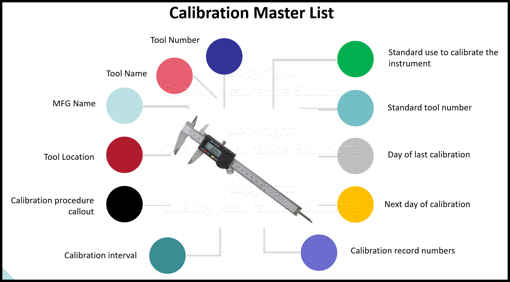
Tool calibration compares a tool’s readings or output with a known reference standard. Accuracy verification then checks whether the measured error meets the required limits. A complete procedure includes inspection, reference checks, repeated measurements, error calculations, uncertainty evaluation, documentation, and corrective action when needed.
In the United States, tool calibration plays a key role in machine shops, auto repair facilities, construction companies, factories, and testing laboratories. Workers use calipers, micrometers, torque wrenches, pressure gauges, and electrical meters to make decisions every day. Even a small measurement error can cause a poor fit, a loose fastener, or a failed quality check. A reliable calibration process helps prevent these problems.
A tool does not stay accurate forever. Regular use can wear its parts. Drops can damage its measuring faces. Heat, dust, moisture, and vibration can also change its readings. These changes may be hard to see during normal work. Calibration helps find them before they affect important results.
A good calibration process does more than compare two numbers. It uses a suitable reference, a clear method, known limits, and records that show what happened. It also separates calibration from adjustment and verification. These steps help workers decide whether a tool can remain in service or needs repair.
This guide covers measuring tools and tools that produce controlled measurements, including dimensional instruments, torque tools, electrical meters, thermometers, and pressure gauges. It explains how to prepare, perform checks, calculate errors, review results, and manage failed tools. The exact method must still follow the tool manual, applicable standards, and the needs of the job.
Source: storage.googleapis.com
What Tool Calibration and Accuracy Verification Mean
Tool calibration is a comparison between a measuring tool and a reference with a known value. The comparison shows how closely the tool agrees with that reference under stated conditions. The result helps users understand the tool’s measurement error.
Accuracy verification takes the next step. It checks the measured results against a stated limit or tolerance. A tool may be calibrated and still fail verification if its error is too large for the intended job.
The National Institute of Standards and Technology, known as NIST, explains that calibration establishes a relationship between reference values and instrument readings. It also involves measurement uncertainty. This means a calibration result is more than a simple statement that a tool is good or bad.
Calibration
A comparison that establishes the relationship between a tool’s readings and known reference values. It records the measured error and related uncertainty.
Verification
A check that provides evidence that the tool meets a stated requirement. The result may be pass, fail, or inconclusive under the chosen decision rule.
Adjustment
A change made to the tool to reduce its measurement error. This may involve a setting, mechanical repair, or electronic correction.
Validation
A wider check that confirms whether a tool or measurement system is suitable for its intended task.
Accuracy, Precision, and Measurement Error
Accuracy describes how close a result is to the correct reference value. Precision describes how closely repeated readings agree with one another. These terms are related, but they do not mean the same thing.
A tool can produce the same wrong reading many times. Such a tool may be precise but inaccurate. For example, a caliper may show 25.06 mm every time it measures a known 25.00 mm reference. Its repeatability is good, but its error is +0.06 mm.
Measurement error is the difference between the indicated value and the reference value. A positive error means the tool reads higher than the reference. A negative error means it reads lower.
Repeatability
The ability of a tool to produce similar readings when the same item is measured under the same conditions.
Resolution
The smallest change in a value that the instrument can display or show.
Tolerance
The allowed range of error or variation for a measurement or process.
Measurement uncertainty
A value that describes the doubt associated with a measurement result.
Why Calibration and Verification Must Remain Separate
Calibration gives the actual measurement data. Verification uses that data to decide whether the tool meets its required limits. A calibration report may include a conformity statement, but the two activities answer different questions.
For example, a micrometer may show an error of +0.004 mm at a certain point. Calibration records that result. Verification checks whether +0.004 mm is acceptable under the tool’s stated tolerance and the applicable decision rule.
Adjustment is different again. It changes the tool. A technician should preserve the original readings before making any change. This record helps show how the tool behaved when it first arrived.
Before adjustment
Record the original condition and all required measurements. These are known as as-found results.
After adjustment
Repeat the required measurements and record the new condition. These are known as as-left results.
Prepare the Tool and Reference Standards Before Calibration
Good preparation makes calibration more reliable. A damaged tool or poor reference can produce misleading results. Start by defining what the tool measures and how accurate the result must be.
Check the manufacturer’s manual before choosing a procedure. Different models can have different measurement ranges, adjustment methods, and test conditions. A general method should never replace a required model-specific procedure.
The reference standard must be more reliable than the tool being checked. It should also cover the measurement range and have a current calibration record. Its uncertainty must be suitable for the required accuracy.
Identify the tool
Record the tool type, manufacturer, model, serial number, measurement range, resolution, and current calibration status.
Define the required accuracy
Find the acceptable error for the work. Check the drawing, work instruction, customer requirement, or applicable standard.
Select a reference
Choose a calibrated gauge block, reference meter, torque tester, temperature standard, or pressure standard that fits the task.
Check the reference certificate
Review its calibration date, assigned values, uncertainty, identification number, and traceability details.
Prepare the work area
Keep the area clean and stable. Reduce dust, vibration, direct sunlight, and other conditions that can affect the result.
Check operator training
Make sure the person performing the work understands the instrument, reference standard, procedure, and safety limits.
Choose a Suitable Reference Standard
A reference standard gives the known value used in a comparison. It may be a gauge block, certified mass, electrical calibrator, pressure controller, or temperature reference. The correct type depends on the quantity being measured.
The reference must have a suitable range and a lower uncertainty than the tool being checked. A common starting guideline is a 4:1 accuracy ratio. This means the reference system is about four times more accurate than the tool requirement. However, this is not a universal rule. The full uncertainty of the method must be considered.
A reference with a current label is not enough by itself. Check its certificate and confirm that its stated range and uncertainty suit the actual calibration.
Dimensional tools
Use suitable gauge blocks, setting rings, reference lengths, or other calibrated dimensional standards.
Torque tools
Use a calibrated torque measurement system that covers the required torque range.
Electrical tools
Use suitable electrical reference sources and measurement standards for the required functions.
Temperature tools
Use a calibrated reference thermometer, temperature bath, or dry-block calibrator.
Control Temperature and Other Environmental Conditions
Temperature can change the size of metal tools and reference standards. This matters when checking small dimensions. A gauge block and a micrometer should have time to reach a stable temperature before the comparison.
Dust, oil, moisture, and small metal chips can also affect contact surfaces. Clean the tool and reference with suitable materials. Avoid touching precision reference surfaces with bare hands when body heat or skin oils could affect the result.
Some electrical and pressure instruments also need a warm-up period or a stable environment. Follow the manufacturer’s instructions and record any conditions that could affect the result.
Clean surfaces
Remove dirt, chips, oil, and other material that may change the contact or measurement.
Allow stabilization
Give the tool and reference enough time to reach the required working temperature.
Reduce vibration
Use a firm work surface and avoid movement during sensitive measurements.
Step-by-Step Tool Calibration Procedures
A reliable calibration follows a written sequence. The procedure should define the test points, reference standards, number of readings, working conditions, calculations, and acceptance rules. This helps different technicians obtain comparable results.
The steps below provide a general framework for measuring tools. The exact test points and methods must come from the manufacturer’s instructions or the applicable technical standard.
Source: automationforum.co
Step 1: Review the calibration procedure
Confirm the tool’s identity, working range, required tolerance, reference standard, and applicable method. Check that the procedure is approved and current.
Step 2: Inspect the tool
Look for cracks, worn surfaces, loose parts, damaged cables, corrosion, bent sections, and other defects. Do not calibrate a tool that is unsafe or clearly damaged without an approved repair process.
Step 3: Clean and prepare the tool
Remove dirt and residue from the measuring surfaces. Follow the manual for cleaning and lubrication. Allow the tool to stabilize before testing.
Step 4: Check the zero position
Close the tool or place it in its defined starting condition. Record the reading. A zero check is useful, but it does not prove that the tool works correctly across its full range.
Step 5: Set up the reference
Install or connect the reference standard according to the approved method. Check its identification, range, certificate, and current status.
Step 6: Record as-found readings
Measure the selected reference values before making any adjustment. Keep the original results even if the tool fails.
Step 7: Test several measurement points
Use points across the working range. Include the lower, middle, and upper portions when the procedure requires them. Add more points when the tool’s use or design calls for them.
Step 8: Repeat the measurements
Take the number of readings required by the procedure. Repeated results help identify poor repeatability, unstable movement, or inconsistent operation.
Step 9: Calculate and review errors
Subtract the reference value from the tool indication. Compare the results with the stated limits and evaluate the measurement uncertainty.
Step 10: Adjust or repair when needed
If the tool fails and adjustment is allowed, use the approved method. Send damaged or complex tools to qualified service personnel when needed.
Step 11: Perform the as-left check
Repeat the required measurements after adjustment or repair. Confirm that the tool now meets the stated requirements.
Step 12: Document and release the tool
Complete the calibration record. Apply the correct status label and return the tool to service only after the required checks are complete.
Signs That Calibration Was Successful
A successful calibration has clear evidence. The tool produces stable readings at the required test points. Its errors are known, and the uncertainty is suitable for the intended work.
The reference standard remains within its valid control status. The operator completes the record and follows the stated acceptance rule. If adjustment took place, the as-left results confirm the change worked.
A tool should not pass just because one reading looks correct. Every required test point and function must meet the procedure.
Stable results
Repeated readings agree within the limits set by the procedure.
Acceptable error
The measured errors meet the stated requirements when uncertainty and the decision rule are considered.
Complete records
All test values, reference details, dates, conditions, and decisions are recorded.
Calibration Methods for Different Types of Tools
These methods are examples, not universal work instructions. A formal calibration must use a procedure suited to the exact instrument, its range, and its intended use. When a tool has a safety-critical role, use a qualified calibration service if the in-house team lacks the required equipment or skill.
Caliper and Micrometer Calibration
Calipers and micrometers are common in U.S. machine shops and production facilities. They help workers check part size, thickness, depth, and other dimensions. Small errors can affect part fit and product quality.
A typical dimensional check uses calibrated gauge blocks or other suitable length standards. The operator places each reference between the correct measuring faces and records the displayed value. The test should cover the working range and the measuring functions used in production.
A zero check alone is not enough. A caliper may read zero correctly and still have errors farther along its scale. Worn jaws, poor alignment, dirt, and excess measuring force can also affect results.
For U.S. caliper work, ASME B89.1.14-2018 (R2023) provides requirements for specification, verification, and calibration. The procedure should also follow the instrument manufacturer’s instructions.
Outside measurement
Check the outside jaws against suitable calibrated length standards.
Inside measurement
Check the inside measuring faces with suitable rings or other approved references.
Depth measurement
Check the depth rod or blade against a suitable reference arrangement.
Measuring force
Use a consistent and suitable force. Avoid squeezing the tool against the reference.
Jaw condition
Inspect for wear, damage, poor alignment, and contact problems.
Torque Wrench Calibration
A torque wrench applies a controlled turning force to a fastener. Its accuracy matters in vehicle repair, equipment assembly, industrial maintenance, and other work where fastener load is important.
A calibrated torque tester or suitable torque measurement system provides the reference. The wrench is tested at the required torque settings and in the correct direction. The operator must apply force at the position and in the manner stated by the applicable procedure.
ISO 6789-2:2017 describes calibration requirements and measurement uncertainty for hand torque tools. It covers indicating and setting torque tools. The ISO catalogue shows that a revision is in development, so users should check the latest edition before approving a formal procedure.
Do not adjust a torque wrench by feel. Do not assume that a click sound proves accuracy. If the tool has been overloaded, dropped, repaired, or used incorrectly, arrange an additional check under the manufacturer’s instructions.
Check the operating range
Use test points that match the wrench’s approved range and intended use.
Use a suitable tester
The torque measurement system must have valid calibration and suitable uncertainty.
Apply the correct force
Follow the specified grip position, direction, and loading method.
Record repeated results
Keep the individual readings so the technician can review variation and error.
Electrical Measuring Tool Calibration
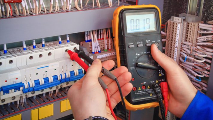
Digital multimeters, clamp meters, and other electrical instruments need suitable electrical references. A calibration source can provide known voltage, current, resistance, or frequency values. The instrument reading is then compared with the expected value.
Testing should cover the functions and ranges that matter for the work. A meter may perform well on DC voltage but show a different error on AC voltage or resistance. Each required function needs its own test method and results.
Electrical calibration can involve dangerous voltages and stored energy. Do not open or adjust an electrical instrument unless trained and authorized. Use qualified calibration personnel and the correct safety equipment.
Voltage
Compare readings with a suitable calibrated voltage source or reference meter.
Current
Use an approved current source or measurement system for the required range.
Resistance
Check suitable resistance points with known reference values.
Additional functions
Check frequency, capacitance, or other functions only when required by the procedure.
Thermometer and Pressure Gauge Calibration
Temperature instruments need a stable reference environment. A calibrated reference thermometer, liquid bath, or dry-block system can provide known temperature points. The instrument under test must reach a stable condition before the readings are compared.
Pressure gauges need a suitable pressure source and reference measurement device. The technician applies controlled pressure and records the gauge reading. Several points may be needed across the working range.
The method should also consider direction of change. Some instruments show different readings when the pressure or temperature rises and when it falls. This behavior can reveal hysteresis or other performance problems.
Temperature stability
Allow the reference and test sensor to stabilize before recording each value.
Pressure control
Increase and decrease pressure in a controlled way when the procedure requires both directions.
Leak inspection
Check pressure connections and the test system for leaks before relying on results.
Sensor placement
Use the correct immersion depth or mounting position for the instrument.
How to Calculate Calibration Error and Verify Accuracy
The basic error calculation is simple. Subtract the reference value from the value shown by the tool. Then compare the result with the allowed error.
The formula is: Measurement error = Tool indication minus Reference value. A positive result means the tool reads high. A negative result means it reads low.
For example, imagine a reference block has a certified value of 25.000 mm. A caliper displays 25.006 mm. The error is +0.006 mm. This means the caliper reads 0.006 mm higher than the reference.
Now assume the allowed error is ±0.010 mm. The measured error is within that basic limit. However, the technician must also consider measurement uncertainty before making a final conformity decision.
Source: automationforum.co
Step 1: Find the error
Subtract the reference value from the tool indication. Keep the sign of the result.
Step 2: Find the allowed limit
Use the tolerance stated in the approved specification or calibration procedure.
Step 3: Review uncertainty
Consider uncertainty from the reference, repeatability, resolution, environment, alignment, and method.
Step 4: Apply the decision rule
Use the agreed rule to decide whether the tool passes, fails, or needs further review.
A Practical Measurement Uncertainty Example
Consider another hypothetical result. A tool has an error of +0.009 mm. The reported expanded uncertainty is ±0.003 mm. The allowed error is ±0.010 mm.
The error plus the stated uncertainty reaches +0.012 mm. That value extends beyond the upper tolerance limit. Under a guard-band decision rule, the result would not qualify as a clear pass.
This does not automatically mean that every decision rule must reject the tool. The applicable standard or agreement may define another method. The important point is to choose the decision rule before testing and apply it consistently.
NIST guidance makes clear that traceability alone does not guarantee that a measurement is fit for its intended purpose. The uncertainty must also be suitable for the decision being made.
Reference uncertainty
The uncertainty stated for the reference standard.
Repeatability
Variation between repeated measurements.
Resolution
The effect of the smallest displayed or readable increment.
Environmental effects
Changes caused by temperature, humidity, vibration, or other conditions.
Method effects
Errors caused by alignment, contact force, setup, or operator technique.
Why a 4:1 Accuracy Ratio Is Not a Complete Answer
A 4:1 ratio is often used as a practical starting point when selecting reference equipment. It helps reduce the chance that the reference will add too much uncertainty to the result.
However, a ratio alone does not prove that a calibration method is suitable. The full measurement process can add uncertainty. The technician must review the reference certificate, setup, repeatability, resolution, and other relevant factors.
A better reference system can improve the result, but the complete method still matters. Use an uncertainty assessment that matches the accuracy required for the work.
Do not rely on labels alone
Check actual reference values and uncertainty in the calibration certificate.
Match the working range
A reference may be suitable at one point but not across the full tool range.
Review the complete method
Include setup and environmental effects when judging whether the process is reliable.
How Often Should Tools Be Calibrated?
There is no single calibration interval that works for every tool. NIST states that it does not set a universal recalibration period for measuring instruments. The right interval depends on the required accuracy, contract or regulatory needs, tool stability, and environmental conditions.
A yearly calibration schedule may be used as an initial plan when it suits the manufacturer’s guidance and the work. It should not be treated as a rule for every instrument. Some tools need more frequent checks because they work in harsh conditions or support critical measurements.
ILAC-G24:2022 and OIML D 10:2022 provide guidance for setting and reviewing recalibration intervals. They support the use of risk, previous calibration results, use patterns, wear, and intermediate checks when setting a suitable period.
Frequency of use
Tools used every day may need closer monitoring than tools used only a few times each month.
Working conditions
Heat, dust, vibration, moisture, and impact can increase the chance of measurement drift.
Required accuracy
A tool used for tight tolerances may need a shorter interval than one used for rough checks.
Past calibration results
Repeated errors close to the allowed limit may show that the current interval is too long.
Manufacturer guidance
Follow stated service and calibration requirements unless an approved quality process sets a stricter rule.
Regulatory and contract needs
Some work may have specific calibration periods or documentation requirements.
Use Calibration History to Improve the Interval
Keep the results from each calibration. Compare the error found on one date with the error found on the next date. This helps show whether the tool is stable or slowly moving toward its limit.
If a tool stays well within its limits over several checks, a qualified person may review whether a longer interval is suitable. If the tool shows poor stability, shorten the interval or replace it.
Control charts can help track changes over time. They show patterns that may not be clear from a single certificate. ILAC-G24 describes several methods for reviewing calibration intervals, including control charts and use-based methods.
Stable performance
Consider whether the interval can be extended through a documented risk review.
Increasing error
Shorten the interval and investigate wear, damage, or environmental causes.
Repeated failures
Review repair costs, tool suitability, and replacement needs.
Perform Intermediate Accuracy Checks
An intermediate check is a quick comparison performed between formal calibrations. It helps confirm that a tool has not changed since its last full calibration. It may use a known reference at one or more important points.
For example, a machine shop may check a frequently used micrometer against a suitable reference at the start of a shift. A torque tool used on critical fasteners may need checks under its approved quality procedure.
An intermediate check does not automatically replace full calibration. It usually covers fewer points and may not provide the same uncertainty data. Record the result and follow the approved action if the check fails.
Before important work
Check tools used for critical measurements against an approved reference.
After unusual events
Perform a suitable check after a drop, overload, repair, or suspected damage.
During regular use
Set check frequency according to risk and the tool’s history.
Calibration Certificates and Traceability Records
A calibration certificate provides evidence of the work performed. It helps the owner understand the tool’s condition on the calibration date. It also gives quality teams a record they can review later.
A good certificate should identify the tool and show the results of the calibration. It should also state the reference standards, measurement uncertainty, and relevant test conditions. A pass or fail statement should identify the requirements and decision rule used.
Metrological traceability means that a measurement result can be linked to a recognized reference through a documented chain of calibrations. Each link contributes to the uncertainty. NIST makes an important distinction: traceability belongs to the measurement result, not simply to a tool, certificate, or laboratory.
Source: automationforum.co
Tool identification
Record the tool name, model, serial number, asset number, and measurement range.
Calibration details
Include the date, procedure, technician, and calibration location.
Reference information
List the reference equipment, certificate numbers, and relevant traceability details.
Measurement results
Show the reference values, tool readings, calculated errors, and measurement uncertainty.
Final status
State whether the tool meets the requirements, fails, or needs further review.
As-found and as-left data
Keep original results and post-adjustment results when an adjustment or repair takes place.
Next calibration date
Record the approved due date or interval based on the organization’s calibration program.
Why ISO/IEC 17025 Accreditation Matters
ISO/IEC 17025 sets requirements for the competence of testing and calibration laboratories. A laboratory accredited to this standard has been assessed for its ability to perform specified technical work.
However, accreditation does not mean that every service offered by the laboratory is covered. Check the laboratory’s scope of accreditation. It should include the measurement type, range, and method needed for the tool.
NIST’s National Voluntary Laboratory Accreditation Program also explains that accreditation covers a laboratory’s technical ability within its stated scope. It does not act as a blanket approval of every result or service.
Check the scope
Confirm that the required measurement parameter and range are listed.
Check the certificate
Review the reported results, uncertainty, and traceability information.
Check the decision statement
Confirm which specifications and acceptance rules were used.
What to Do When a Tool Fails Calibration
A failed calibration needs a clear response. Do not return the tool to normal work just because it still turns on or gives a reading. First, protect the quality of any work that depends on its measurements.
The first step is to remove the tool from use. Mark it as out of service and keep it separate from tools that have passed. This prevents another worker from using it by mistake.
Next, review the as-found results. Identify the points where the error exceeded the limit. Check whether the problem came from wear, damage, incorrect setup, poor handling, or a faulty reference system.
The quality team should also review measurements made since the last known acceptable check. The risk depends on the size of the error, the type of work, and the decisions made using the tool. This review helps identify parts or records that may need further inspection.
Step 1: Stop use
Remove the tool from service and apply a clear warning label.
Step 2: Preserve evidence
Keep the original readings, certificate, inspection notes, and tool identification.
Step 3: Find the cause
Inspect the tool for wear, damage, loose parts, contamination, and incorrect settings.
Step 4: Review earlier work
Identify products, jobs, or test results that may have been affected since the last acceptable check.
Step 5: Repair or adjust
Use an approved repair or adjustment method. Replace damaged parts when needed.
Step 6: Recalibrate
Repeat the required tests and confirm the as-left condition.
Step 7: Approve release
Return the tool to service only after the responsible person approves the results.
When a Tool Should Be Replaced
Not every failed tool should be repaired. Some tools have worn measuring faces, damaged internal parts, or unstable electronics. Repair may cost more than replacement or may not restore reliable performance.
Replacement may be the better choice when the tool repeatedly fails, cannot meet the required uncertainty, or has no available service support. The replacement should have a suitable range and accuracy for the work.
A new tool also needs to enter the calibration system. Do not assume that a new instrument will remain accurate without an initial check or the manufacturer’s required calibration records.
Repeated failure
The tool continues to fail after approved repairs or adjustments.
Severe damage
Important measuring surfaces or internal parts cannot be restored to the required condition.
Poor suitability
The tool cannot meet the accuracy or uncertainty needs of the task.
High repair cost
Replacement provides a more practical and reliable long-term option.
Common Calibration Mistakes and Safety Limits
Many calibration problems come from poor setup rather than a faulty instrument. A dirty reference, unstable workbench, or incorrect test point can change the result. A clear procedure helps prevent these errors.
Workers should also understand the limits of in-house checks. A simple comparison may be useful for routine monitoring, but it does not always provide a formal calibration with traceable uncertainty. Use a qualified laboratory when the required method or equipment is beyond the team’s ability.
Checking only the zero position
A correct zero reading does not prove that the tool is accurate across its full range. Test the required points and functions.
Using an unsuitable reference
A reference with poor accuracy or an unsuitable range can make the result unreliable.
Ignoring uncertainty
A reading inside the tolerance may still need further review when uncertainty is large.
Adjusting before recording as-found data
This removes useful evidence about the tool’s original condition.
Using the wrong measurement force
Excess force can affect dimensional readings and may damage sensitive measuring faces.
Ignoring environmental conditions
Temperature changes, vibration, and contamination can affect the measurement.
Missing calibration records
Without complete records, it becomes harder to prove that a tool was suitable for the work.
Using an expired reference
Check the reference’s status and follow the organization’s rules before relying on its values.
Returning a failed tool to service
A tool must pass the required checks before normal use resumes.
Know When Professional Calibration Is Necessary
Some tools need specialist equipment and trained technicians. Electrical meters, pressure instruments, precision torque tools, and high-accuracy dimensional equipment may require controlled systems and detailed uncertainty calculations.
Never open a high-voltage instrument or a pressurized system without the correct training and isolation steps. Follow the relevant safety procedure and the manufacturer’s service instructions.
If the tool supports a safety-critical measurement, customer acceptance, or regulated process, use a calibration provider whose technical scope matches the task. A quick shop-floor check may not provide enough evidence.
Electrical hazards
Use qualified personnel for high-voltage work, electrical calibration, and internal instrument repairs.
Pressure hazards
Use rated connections and controlled pressure sources. Release pressure safely before changing connections.
Mechanical hazards
Secure heavy equipment and avoid exposed moving parts during calibration.
Precision work
Use suitable laboratory facilities when the required uncertainty cannot be achieved in-house.
Important Questions to Answer After Calibration
Calibration is part of a wider measurement control process. Once a tool has been checked, the owner still needs to decide how it will be used, monitored, and maintained. The following questions address practical needs that often arise before, during, and after calibration.
The questions about calibration intervals and the difference between calibration and verification are observed topics in the NIST, Fluke, CASRAI, and Instron guidance reviewed for this article. The questions about failed tools and in-house capability are inferred next needs based on the calibration workflow and its possible consequences.
Observed question: How often should a tool be calibrated?
Reader stage: Before scheduling. Reviewed guidance explains that intervals depend on stability, use, environmental conditions, and requirements. This guide adds a practical method for using historical results to review the interval.
Observed question: What is the difference between calibration and verification?
Reader stage: Before testing. Reviewed guides explain the difference in meaning. This article connects the terms to actual measurement errors, tolerance limits, and pass or fail decisions.
Inferred next need: What happens when a tool fails?
Reader stage: After testing. The practical need follows from an out-of-tolerance result. This guide explains isolation, impact review, repair, recalibration, and release.
Inferred next need: Can workers perform calibration in-house?
Reader stage: Planning. The answer depends on competence, reference equipment, uncertainty, and the required standard. This guide separates routine checks from formal calibration.
Inferred next need: What should a calibration certificate contain?
Reader stage: After calibration. The reader needs evidence that supports future decisions. This guide identifies the key records, results, and reference details to review.
Build a Simple Tool Calibration Control System
A basic control system can prevent missed calibration dates and accidental use of failed tools. Start with a register that lists each measuring tool and its status. Give each tool a unique asset number.
Set up reminders for due dates and define who can approve calibration results. Keep certificates in a central location. Make sure workers know how to identify tools that are out of service.
Review the register at planned intervals. Look for repeated failures, missing records, overdue tools, and tools that are no longer suitable for the work. This review helps improve the calibration program over time.
Maintain an asset register
List tool details, locations, calibration dates, and current status.
Assign responsibility
Identify the people who manage calibration, perform checks, and approve release.
Store records
Keep certificates, repair records, intermediate checks, and failure reports.
Review performance
Use past results to improve intervals and reduce repeat failures.
Frequently Asked Questions
Q
What is the difference between tool calibration and accuracy verification?
Calibration compares a tool with a known reference and records its measurement error and uncertainty. Accuracy verification checks whether those results meet a defined requirement. Calibration provides measurement data, while verification makes a conformity decision.
Q
Can I calibrate measuring tools myself?
Yes, some organizations can perform in-house calibration when they have trained personnel, suitable reference standards, approved procedures, and adequate uncertainty control. A simple check against a known reference is not automatically a formal calibration. Use an accredited laboratory when the required technical capability or documentation is not available in-house.
Q
How often should measuring tools be calibrated?
There is no universal interval for every tool. A suitable schedule depends on the manufacturer’s guidance, required accuracy, frequency of use, working conditions, historical results, and any contract or regulatory requirements. Review the interval when the tool shows unusual drift or repeated failures.
Q
Does a calibration certificate guarantee that a tool will remain accurate?
No. A calibration certificate reports the tool’s condition under stated conditions at the time of calibration. The tool can change later due to wear, impact, temperature, or poor handling. Routine care and suitable intermediate checks help detect changes between formal calibrations.
Q
Does a zero check prove that a tool is accurate?
No. A zero check only confirms the starting indication under that condition. A tool can show zero correctly and still have errors at other points. A complete procedure checks the required range and functions against suitable reference standards.
Q
Should a tool be recalibrated after being dropped or repaired?
A drop, overload, repair, or other event may change the tool’s performance. Remove it from critical work and follow the manufacturer’s instructions and your quality procedure. Perform an appropriate verification or full recalibration before returning it to service.
✦ Wrapping Up
Conclusion
Tool calibration procedures and accuracy verification help protect measurement quality in workshops, factories, laboratories, and service facilities across the United States. A reliable process compares the tool with a suitable reference, records the error, evaluates uncertainty, and checks the result against defined limits.
The best calibration program uses clear procedures and trained workers. It keeps as-found and as-left records, controls reference standards, and sets intervals based on real tool performance. It also has a clear plan for failed tools.
Remember that calibration does not make a tool accurate forever. Every tool needs proper handling, suitable storage, routine checks, and timely service. When the required accuracy is beyond the available in-house equipment or skill, a qualified calibration laboratory is the safer choice.
💡 Key Takeaway
Start by creating a register of all measuring and torque tools. Record each tool’s range, required tolerance, reference standard, calibration status, and next due date. Then create a written procedure that includes inspection, as-found readings, multiple test points, uncertainty review, acceptance rules, and as-left checks. Remove failed tools from service until their status has been confirmed.
Tool Manufacturing Processes Quality Control and Defect Prevention starts with clear specs, stable processes, sound checks, and effective root-cause action.