Tool speed ratings show how fast a tool can run. Variable speed lets you adjust that rate to suit the job, material, and safe operating limits.
In the United States, power tools are used each day in home shops, garages, building sites, and repair bays. A drill may need to turn slowly to drive a large screw. A router may need a lower speed when it holds a wide cutter. A sander may need a change in speed to help control heat and surface marks. The right speed depends on the task, not just the highest number on the tool.
Many U.S. tool makers list speed in revolutions per minute, or RPM. Some list one speed, while others show a range. A drill may show 0 to 500 RPM in low gear and 0 to 1,900 RPM in high gear. That does not mean it will hold each of those speeds while cutting or drilling. Speed can fall as the motor meets resistance.
Speed also affects heat, cutting action, finish quality, and control. Too much speed may damage a bit, scorch wood, or exceed an attachment’s safe limit. Too little speed can cause poor cutting, chatter, or a stalled motor. The goal is to find a suitable working speed and maintain it without forcing the tool.
This guide explains how to read speed ratings, use variable-speed controls, and select a suitable operating range. It also covers speed loss under load, simple calculations, safe setup, and common problems. The examples use documented tool functions and basic mechanical principles. They are not results from hands-on product testing.
Source: ukam.com
How to Read Tool Speed Ratings Correctly
A tool speed rating describes how fast a moving part runs under specified conditions. For a drill, the rating often refers to the chuck or spindle. For a router, it refers to the motor-driven spindle that holds the cutter. For a belt sander, a separate rating may describe how fast the abrasive belt moves.
The first step is to identify what the number measures. Revolutions per minute describe rotation. Strokes per minute describe repeated back-and-forth motion. Blows per minute describe impacts on tools such as hammer drills. These units measure different actions, so they should not be compared as though they mean the same thing.
Next, check whether the stated speed is a maximum, a working range, or a no-load figure. A range such as 0 to 2,000 RPM usually describes variable operation up to a stated speed in a given mode. It does not guarantee stable operation at every point in that range.
The tool’s model, selected gear, battery condition, and working resistance also matter. A speed figure is useful only when it is tied to the correct operating conditions. A product label or manual should define the rating more clearly than an advertising headline.
Source: ukam.com
Maximum RPM
The highest stated rotational speed under the specified test or operating conditions. It is not a recommendation to run at maximum speed for every task.
No-Load RPM
The speed when the tool runs without significant cutting or working resistance. The speed can drop once the tool contacts the material.
Operating Speed
The actual speed during work. It depends on the selected setting, load, motor behavior, and control system.
Variable-Speed Range
The range that the control system can command. The usable range under load may be more limited than the stated no-load range.
What Does a Two-Speed Drill Rating Mean?
A two-speed drill uses different gear ratios to provide two operating ranges. Low gear favors controlled rotation and greater torque multiplication at the spindle. High gear favors faster rotation when the task needs less torque.
For a documented U.S. example, the Makita XPH17 hammer driver-drill is listed with variable two-speed ranges of 0 to 500 RPM and 0 to 1,900 RPM. The first range is suited to tasks that need slower rotation and higher available output torque. The second provides higher no-load speed for suitable drilling and driving work.
Those figures come from the maker’s specifications. They do not establish the exact speed the drill will hold when a particular bit meets a particular material. The gear setting, trigger position, bit size, and cutting load still affect the result.
Why a Higher Speed Rating Does Not Always Mean Better Performance
A tool with a higher maximum RPM is not always the better tool for a heavy job. Torque, available power, gearing, attachment design, and the ability to maintain speed all influence useful performance.
For example, a drill that spins fast with no load may slow sharply when a large bit enters dense material. Another drill may have a lower maximum RPM but offer better control and more useful torque in low gear. Comparing the two only by their highest RPM would miss that difference.
Speed is one part of the performance picture. The correct question is whether the tool can maintain a suitable speed while doing the required work.
How Variable-Speed Controls Affect Tool Performance
Variable speed lets an operator change how fast the tool moves without replacing the tool. It can help match the work to the material, improve control, and reduce some forms of surface damage. The result depends on how the tool controls its motor and how much load it can handle.
Not all variable-speed tools work in the same way. A trigger may change the motor’s commanded speed as it is pressed. A dial may establish a target speed. A mechanical gear selector changes the ratio between motor speed and output speed. Some tools combine these controls.
Electronic speed control can also affect how well a tool responds when the load changes. A basic controller may reduce motor power or drive pulses to slow the tool. A feedback controller can monitor motor behavior and adjust the power supplied to resist a drop in speed.
That difference becomes useful when a cutting tool passes from easy material into a denser section. A system that maintains a more stable speed may produce a more even cutting action. However, no electronic controller can provide unlimited power or prevent every stall.
Source: ukam.com
Variable Trigger
Allows quick changes in speed as the operator presses or releases the trigger. It is useful for controlled starts and short tasks.
Speed Selection Dial
Sets a target speed or speed band. It can help maintain a repeatable setting during longer tasks.
Mechanical Gear Selector
Changes the relationship between motor speed and output torque. It is useful when moving between fast, light work and slower, heavier work.
Electronic Feedback Control
Adjusts motor input as load changes to help maintain the selected speed within the tool’s operating limits.
How Electronic Speed Control Works Under Load
When a cutter enters wood or metal, the material resists its motion. That resistance places more load on the motor. If the tool cannot supply enough torque at the selected speed, the spindle slows.
Electronic feedback systems attempt to limit this drop. Bosch, for example, documents Constant Response circuitry on its PR20EVS palm router. The maker states that this system monitors speed and helps maintain it as load changes. The same product has a specified variable-speed range of 16,000 to 35,000 RPM.
This is evidence of a documented control function, not proof that the router holds exactly the same RPM under every load. The size of the cutter, cut depth, feed rate, and material can still exceed the motor’s practical capacity.
Does Lower Speed Always Increase Torque?
No. The way speed is reduced makes a difference. Selecting a lower mechanical gear normally increases the torque multiplication available at the output, though the motor and drivetrain still have limits.
Reducing speed with an electronic trigger or dial does not automatically produce the same torque benefit. Motor design, control method, and available current determine what torque the tool can provide at low RPM.
A motor that runs very slowly under a heavy load may also have less effective cooling. This is especially relevant to tools that depend on motor-driven airflow. If the tool becomes hot, stalls often, or triggers overload protection, reduce the load and follow the manual’s cooling instructions.
How to Select the Right Speed for Each Material and Tool
The correct operating speed depends on the tool, attachment, material, and type of work. There is no single RPM that works for all drilling, cutting, sanding, or grinding jobs.
Cutting tools often need different speeds as the cutter diameter changes. Larger cutters move faster at their outer edge at the same spindle RPM. Material hardness, cutting-edge design, cooling, and feed rate also influence the safe and effective setting.
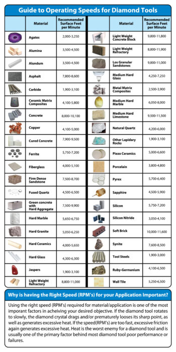
A sensible starting point is the speed guidance from the tool and accessory makers. If the two sets of instructions differ, do not exceed either product’s stated operating limits. A speed chart is a starting aid, not permission to ignore a cutter’s marked limit.
The following examples explain common speed choices. They are general operating principles, not universal RPM prescriptions. Exact values should come from documentation for the bit, blade, wheel, and material being used.
Source: ukam.com
Small Drill Bits
Small cutting diameters often require higher spindle RPM to reach a specified cutting speed. The bit material and workpiece still set the limits.
Large Drill Bits
Large bits generally need lower RPM for a given cutting speed. They also place more torque demand on the drill.
Router Bits
Large-diameter bits often require lower RPM than small bits. Follow the router and cutter maker’s limits, including any restrictions on handheld use.
Sanders
Speed affects cutting action, heat, and control. Abrasive grit, pressure, backing pad, and material can change the result.
Grinders
Wheel compatibility and maximum rated speed are safety limits. A variable-speed control does not make an incompatible wheel safe.
Understanding Surface Speed and RPM
RPM counts turns per minute. Surface speed describes how far a point on the outer edge travels in a set time. The distinction matters because a large cutting edge travels farther on each turn than a small one.
In U.S. machining work, surface speed is often expressed in surface feet per minute, or SFM. For a rotating part with a diameter measured in inches, the basic formula is SFM = 3.1416 × diameter × RPM ÷ 12.
Consider a hypothetical 1-inch cutter turning at 12,000 RPM. Its outer edge moves at about 3,142 surface feet per minute. A 2-inch cutter at the same spindle speed has an outer-edge speed of about 6,283 surface feet per minute.
This calculation shows why cutter size matters. It does not establish a safe cutting speed. Each cutter has limits based on its construction, material, mounting, and intended use.
Choosing Drill Speeds for Wood and Metal
For conventional rotary drilling, larger bits usually require slower spindle speeds than smaller bits when the goal is to maintain a similar cutting speed. Metal type, drill-bit material, hole depth, and lubrication affect the setting. An ordinary drill bit used in mild steel may need a different speed from the same diameter bit used in aluminum or stainless steel.
A simple hypothetical calculation makes the relationship clear. If a cutting-speed reference calls for 100 SFM, a 1/4-inch bit would need about 1,528 RPM. A 1/2-inch bit would need about 764 RPM. The target surface speed remains the same, but the larger bit turns at half the rate.
These figures are math examples, not recommended cutting speeds for every material or bit. In practice, the operator must use the applicable bit manufacturer’s data and the drill’s approved speed range.
For hand drilling, workpiece support is also vital. Clamp loose material rather than holding it by hand. A large bit can grab and twist the drill or workpiece. Use suitable handles, bits, and operating methods to control that risk.
Matching Router and Sander Speed to the Work
Router speed affects cutter-edge velocity, chip formation, heat, and the quality of a cut. Large cutters often require reduced RPM. A shallow pass can lower the load on the motor, but it does not raise the cutter’s maximum permitted RPM.
A sander behaves differently because the abrasive works over many small contact points. High speed, hard pressure, worn abrasive, and poor dust removal can combine to increase heat or leave unwanted marks. Lower speed can improve control on some finishes, but it may also reduce material removal.
The best setting is one that keeps the tool stable, removes material as intended, and stays within the limits of the accessory. Test on scrap when practical, and use the result to refine the setting rather than assuming that full speed is always better.
A Safe Step-by-Step Method for Setting Tool Speed
Safe speed selection starts before the tool runs. The operator needs the correct attachment, the product instructions, a stable workpiece, and suitable personal protective equipment. If the tool or accessory has an unknown rating, do not guess at a safe maximum speed.
First, identify the task. Note the material, hole or cutter diameter, cut depth, and expected load. Check the accessory instructions for any required speed range, maximum RPM, feed guidance, and limits on the tool type.
Next, select the correct mechanical gear or speed band while the tool is stopped, unless the maker explicitly permits adjustment while running. Set a suitable initial speed according to the instructions. Keep hands away from moving parts, secure the work, and position the tool so it can be controlled if the bit catches.
Make a controlled test where the work and tool allow it. Watch the cutting action, motor sound, vibration, heat, and finish. If the material burns, the tool chatters, or the motor slows sharply, stop and identify the cause before changing the setting.
Source: ukam.com
Step 1: Confirm Compatibility
Check the tool model, attachment size, mounting type, rated speed, and approved use. Reject damaged or unsuitable accessories.
Step 2: Prepare the Work Area
Secure the workpiece. Fit required guards, handles, dust controls, and protective equipment. Clear the area of loose items.
Step 3: Select the Initial Range
Use the manufacturer-recommended speed or a suitable setting within the permitted range. Select the correct gear if the tool has one.
Step 4: Start With Control
Hold the tool as instructed and let it reach the required speed before contacting the work when that procedure applies. Follow any tool-specific starting method.
Step 5: Apply a Suitable Feed
Guide the tool at a rate that permits a stable cut. Do not push harder simply to make a stalled tool continue.
Step 6: Inspect the Result
Check the finish, chips or dust, tool behavior, and any signs of excess heat. Adjust only after considering the likely cause.
Signs That the Selected Speed Is Working
A suitable setting produces a stable cutting or finishing action for the task. The tool should respond in a controlled manner, and the attachment should remove material as intended without abnormal vibration, repeated stalling, or excessive heat.
For drilling, suitable chips and steady progress can indicate that the bit is cutting rather than rubbing. For routing, an even cut without burning or heavy chatter is a useful sign. For sanding, the surface should improve without deep swirl marks, melting, or scorching.
These signs do not prove that the RPM is safe. A smooth-looking result cannot replace a check of the tool and accessory ratings. Speed limits remain mandatory even when the work appears normal.
What to Do When the Test Does Not Work
If the tool stalls, binds, becomes unusually hot, or vibrates more than normal, release the control and let moving parts stop. Disconnect the power supply or remove the battery before inspecting or changing an accessory, following the maker’s instructions.
Check for a dull or damaged bit, excessive cut depth, poor work support, incorrect gear, blocked dust removal, or an unsuitable feed rate. A speed change may help, but it will not fix every cause.
If the tool repeatedly overheats, makes abnormal mechanical sounds, shows damaged wiring, or cannot hold a suitable speed under normal rated use, stop operating it. Seek inspection by a qualified repair technician or an authorized service center.
Common Speed Mistakes, Safety Limits, and Buying Decisions
The most serious speed mistake is treating a tool’s speed control as a substitute for accessory compatibility. An attachment may have its own maximum RPM, diameter limit, mounting requirements, and restrictions on the type of machine that can drive it. All those conditions matter.
Abrasive wheels need special care because overspeed can cause wheel failure. OSHA’s U.S. abrasive-wheel machinery rule, 29 CFR 1910.215, requires checking machine spindle speed against the wheel’s marked maximum operating speed before mounting. OSHA also provides grinder inspection guidance that includes guards, wheel condition, and RPM compatibility.
A wheel marked for a lower maximum RPM than the grinder’s maximum spindle speed must not be assumed safe merely because the grinder has a dial. Use only a combination the applicable manufacturer instructions approve, and follow the relevant workplace safety requirements.
Another common mistake is assuming a speed controller can solve weak performance. A tool may need a different gear, a sharper attachment, a lighter cut, or a higher-capacity motor. A larger maximum RPM figure is not a replacement for sufficient torque, power, cooling, and duty capacity.
Source: ukam.com
Running Every Tool at Full Speed
Maximum speed may be wrong for the cutter, material, or finish. Choose the speed required by the task and the applicable instructions.
Ignoring Accessory Ratings
Blades, wheels, pads, and cutters can have separate operating limits. Confirm those limits before use.
Forcing a Tool That Slows Down
Heavy feed pressure can increase load, heat, and binding. Reduce the load and inspect the setup instead of forcing progress.
Assuming Low RPM Is Always Safe
Slow rotation can still produce high torque, a grab, poor cutting, or motor overheating. Low speed is not a substitute for guarding and control.
Comparing Only Maximum RPM
A high no-load figure says little about speed stability, low-speed torque, speed adjustment, or performance during continuous work.
What Matters When Comparing Two Variable-Speed Tools?
Start by matching each tool to the same job. Compare the documented operating ranges, gear options, type of control, rated capacity, and approved accessories. A tool that offers a very high maximum speed may still lack the slow operating range needed for a large drill bit.
Control quality matters as well. A smooth trigger may make short fastening tasks easier. A speed dial may suit a long routing operation that needs a repeatable setting. Mechanical gearing may be more important when the job requires high torque at low spindle speed.
For frequent or heavy work, check how the tool handles sustained load, heat, and overload conditions. Manufacturer specifications describe intended functions, but a claim about which model performs better under load needs comparable independent testing or reliable measurements.
Control Method
Check whether the tool has a trigger, dial, mechanical gears, electronic feedback, or a combination.
Useful Speed Range
Check whether the tool reaches the speeds required for the actual work, not just whether its maximum RPM is high.
Load Handling
Review rated capacity, motor behavior, cooling limits, and any documented overload protection.
Accessory Fit
Confirm supported sizes, mounting systems, guards, and approved operating methods.
Important Questions to Answer Before the Next Job
Before starting a new job, identify the main unknown. A worker moving from a small bit to a large bit needs to check diameter and cutting speed. Someone changing from softwood to metal needs to review bit type, cutting speed, lubrication, and work support.
The next question may concern performance rather than speed selection. If a tool repeatedly slows during normal work, the cause could be excessive feed, an unsuitable accessory, low battery charge, motor protection, or a mechanical fault. Those possibilities call for different checks.
It is also useful to ask whether the rated speed refers to the motor, the spindle, or a moving belt. Confusing these values can lead to poor comparisons. Some accessories have separate limits expressed in RPM or surface speed, which must be interpreted in the correct units.
The final decision should be based on the permitted operating range and the required result. If the necessary speed falls outside the tool’s approved capabilities, a different tool or attachment may be needed. Do not modify safety controls or bypass speed restrictions to force compatibility.
Frequently Asked Questions
Q
Is Variable Speed Better Than Fixed Speed for Power Tools?
Variable speed is more flexible when a tool handles different materials, cutter sizes, or tasks. It allows the operator to select a suitable speed instead of using one fixed setting.
Fixed speed can still work well when a machine is designed for a narrow range of operations. The main issue is whether the speed matches the intended use. Variable control alone does not guarantee more power, better results, or greater safety.
Q
Why Does My Tool Slow Down When I Apply Pressure?
A rotating tool slows when the load demands more torque than the motor can provide at the selected speed. A dull bit, excessive feed, deep cut, wrong gear, or unsuitable material can increase the load.
Battery condition and thermal or overload protection can also affect some cordless tools. Reduce pressure, check the attachment, and follow the maker’s instructions. If unusual slowing continues under normal use, stop and have the tool inspected.
Q
Can a Variable-Speed Drill Work at Very Low RPM?
Many variable-speed drills can turn slowly when the trigger is pressed lightly. However, that does not mean they can provide steady, high torque at every low-speed setting.
For a demanding job, use the appropriate mechanical gear when available. Check the drill’s rated capacity and avoid holding the motor near a stall for long periods. A drill press or other suitable machine may offer better control for certain work.
Q
How Do I Know Whether an Attachment Can Handle My Tool’s RPM?
Read the maximum speed marked on the attachment or stated in its official instructions. Compare that limit with the applicable maximum spindle speed of the tool. The attachment must also match the machine type, mounting system, size restrictions, and required guards.
For example, if a grinder can run at 11,000 RPM, a grinding wheel rated for only 8,500 RPM is not a suitable match at that speed. Do not assume reducing the dial makes it acceptable unless the manufacturer explicitly approves that arrangement.
Q
Can RPM Alone Tell Me Which Power Tool Is More Powerful?
No. RPM measures rotational speed, not power by itself. Mechanical output power depends on both torque and rotational speed.
Two tools may have similar maximum RPM but different torque curves, motor ratings, gearing, and performance under load. To compare useful output, examine the complete specifications and reliable tests under matching conditions. A high free-running speed is not evidence of greater cutting capacity.
✦ Wrapping Up
Conclusion
Tool speed ratings help explain how fast a machine can run, but they do not tell the whole story. The useful speed depends on the material, attachment, job size, and load. Variable speed gives the operator more ways to match the tool to those needs.
A low mechanical gear can help with slow, demanding work. Electronic controls may help regulate speed as load changes. A high-speed setting may suit some light cuts, but maximum RPM is not a general target. Each function has limits that need to be understood before the tool runs.
The key safety rule is to respect both the machine and accessory ratings. Use the specified guards, secure the work, and stop if the tool binds, overheats, or behaves abnormally. A speed adjustment cannot make an unsuitable attachment safe.
When choosing a tool, look beyond the highest RPM. Consider the working range, speed stability, available torque, control features, and the job the machine must perform. Those factors provide a more useful picture of real operating capability.
💡 Key Takeaway
Before the next job, check the tool’s speed range and the attachment’s operating limits. Choose the correct gear and initial setting, secure the work, and make a controlled test. Adjust only within the approved range, and stop if the tool shows signs of overload or unsafe operation.