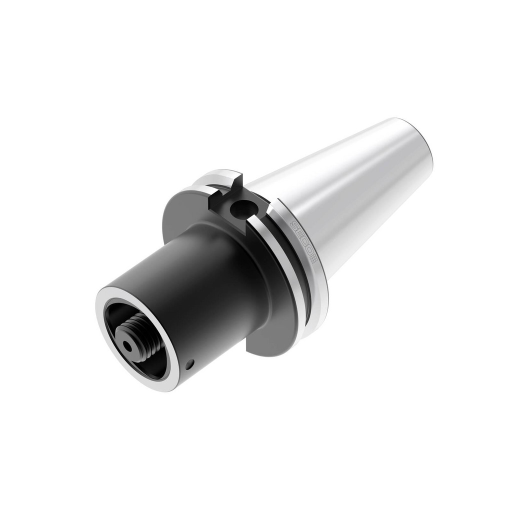
Tool adapter, coupler, and interface systems connect machine spindles, tool holders, and cutting tools. The correct system must match the machine, transfer torque, maintain alignment, and hold the tool securely during operation.
Across manufacturing shops in the United States, CNC mills, lathes, machining centers, and other production machines rely on secure tool connections. A tool adapter helps connect parts with different sizes or connection types. A coupler joins compatible components. An interface system controls how those parts fit, align, and transfer force. Each part has a clear job.
Choosing the right connection takes more than matching two parts by appearance. Spindle taper, flange shape, locking method, tool size, speed, and cutting load all matter. A poor match can cause vibration, tool movement, bad surface finish, or damage to costly machine parts. This guide explains the main systems, how to check compatibility, and how to install and care for each connection.
Source: mscdirect.com
What Are Tool Adapter, Coupler, and Interface Systems?
These systems form the connection between a machine and the tool that does the work. They are common in CNC machining, drilling, milling, turning, and other industrial tasks. Their main job is to keep parts aligned while passing force and motion from one part to another.
The three terms describe related parts, but they do not mean the same thing. Knowing the difference helps prevent buying the wrong component or building an unsafe tool assembly.
A complete system may use several connections in a row. Each connection must fit the parts on both sides. It must also handle the force, speed, and working conditions of the task.
Source: mscdirect.com
Tool Adapter
An adapter links two parts that have different connection sizes, shapes, or designs. For example, a machine-side adapter may connect a spindle type to a modular toolholding system. A reduction adapter may allow a smaller tool holder to fit a larger compatible assembly.
Tool Coupler
A coupler joins two matching parts. It may use a taper, polygon, threaded joint, locking bolt, cam, or another approved locking method. It must keep the parts together while transmitting the required force and torque.
Tool Interface
An interface is the designed contact and connection area between two components. It controls fit, alignment, retention, and, in many systems, torque transfer. Its dimensions and tolerances determine whether two parts can work together.
Modular Toolholding System
A modular system uses standard adapters, extensions, reducers, and tool heads to build different assemblies. A shop can use a smaller group of parts for many jobs instead of keeping a separate complete holder for every task.
Why These Components Matter
A cutting tool must stay in the correct position during work. Even a small shift can affect the size and finish of a machined part. A weak connection can also cause chatter, excess heat, or tool breakage.
A well-matched interface helps the tool run in line with the spindle. It also makes tool changes more repeatable. This matters in a production shop where the same job may run across several shifts.
Better Alignment
A close and correct fit helps keep the tool centered and reduces unwanted movement.
Secure Retention
A suitable locking system keeps the tool holder in place during cutting and tool changes.
Flexible Setup
Modular parts allow workers to build different tool lengths and arrangements from standard components.
How a Tool Adapter and Coupler Assembly Works
A toolholding assembly works as a connected chain. The machine spindle holds the machine-side tool holder. An adapter may connect that holder to a modular coupling. Another adapter or tool head then holds the cutting tool.
Each part has a set position. The machine-side connection must match the spindle. The middle connection must match the modular system. The final connection must hold the actual cutting tool.
Think of the assembly as a chain of links. Every link must fit the next one. A strong cutting tool cannot make up for a weak or poorly matched connection elsewhere in the chain.
Source: mscdirect.com
Machine Spindle
The spindle provides rotation and holds the main tool assembly. Its taper, size, face, and retention design determine the required machine-side interface.
Machine-Side Adapter
This component connects the spindle standard to a compatible modular toolholding system. It may have a BT, CAT, SK, HSK, or another approved machine connection.
Modular Coupler
The coupler joins the adapter to another modular part. It helps keep the assembly centered and transfers the required torque through its designed contact surfaces.
Extension or Reduction Adapter
An extension increases the distance between the spindle and cutting edge. A reducer changes the connection size when the system allows it.
Tool Holder
The tool holder grips the cutting tool. Common designs include collet chucks, hydraulic holders, shrink-fit holders, and end mill holders.
Cutting Tool
The cutter, drill, boring bar, or other working part removes material. Its size, weight, speed rating, and cutting load affect the full assembly.
How Force Moves Through the Assembly
The spindle supplies rotation. The holder and its connections pass that rotation to the cutting tool. The contact surfaces and locking parts keep the assembly in position as cutting forces act on it.
The exact force path depends on the interface design. Some systems use friction and clamping force. Others use shaped contact surfaces, keys, or polygonal features to transfer torque. The manufacturer defines how each system must be assembled.
Rotation
The connection must transfer the torque needed for the cutting task without slipping.
Position
The contact surfaces must keep the tool aligned with the machine spindle.
Retention
The locking parts must hold the assembly under the forces and speeds allowed by the system.
Common Machine-Side Tool Interface Systems
Machine-side interfaces come in several designs. The spindle specification decides which one a machine needs. A similar size or taper angle does not prove that two systems are compatible.
In American machine shops, CAT and other 7:24 taper systems are common. Imported machines may use BT, SK, or HSK designs. Some machines also use polygonal quick-change systems.
Before buying an adapter, check the machine model, spindle specification, holder drawing, and retention method. Do not select a connection from a product photo alone.
Source: mscdirect.com
BT Interface
BT holders use a 7:24 steep taper and a specific flange and pull-stud design. They are common on many Asian-built machining centers. The exact size and pull-stud specification must match the machine.
CAT Interface
CAT holders also use a 7:24 steep taper. They have their own flange and retention details. CAT holders are widely used on North American machining centers. A CAT holder is not automatically interchangeable with a BT holder of the same nominal size.
SK or ISO Steep Taper
SK holders use a 7:24 taper and their own flange and pull-stud specifications. A matching taper angle alone does not make an SK holder compatible with CAT or BT equipment.
HSK Interface
HSK uses a hollow, short taper with contact at the taper and flange. It uses an internal clamping system rather than the pull-stud arrangement found on many steep-taper holders. HSK forms and sizes must still match the machine.
Polygonal Taper Interface
Polygonal systems use shaped contact surfaces to locate the tool and transmit torque. Seco-Capto is one example of a modular system based on Polygonal Shank Coupling. The relevant product size and clamping method must match.
Proprietary Quick-Change Interface
Some manufacturers use their own quick-change designs. These may offer fast head changes or special locking features. Check the exact product family because a similar-looking part from another system may not fit.
Why Similar Taper Sizes Are Not Enough
A CAT40 and BT40 holder may look alike because both use a 7:24 taper. However, their flange details and pull-stud requirements can differ. A wrong holder may fail to seat or clamp as designed.
The same rule applies to other interface families. A matching number does not always mean a matching connection. Never force a holder into a spindle to test whether it fits.
Check the Full Standard
Confirm the interface family, size, flange, drive features, and retention parts.
Check the Machine Manual
Use the exact spindle and pull-stud information for the machine model.
Confirm Special Variants
Dual-contact and other special designs may require a matching spindle and holder combination.
Types of Tool Adapters and Couplers
Adapters and couplers are designed for different jobs. Some connect the machine to a modular system. Others change tool size, increase reach, or allow a different cutting head to be used.
The right design depends on the work. A short, solid adapter may suit a rigid milling setup. An extension may be needed to reach a deep feature. A quick-change coupler may help when a shop changes cutting heads often.
Source: mscdirect.com
Machine Interface Adapters
These connect a machine spindle standard to a modular toolholding family. They are useful when a shop wants to use one modular tooling range across machines with different spindle connections.
Extension Adapters
Extensions increase tool reach. They help when a cutter must reach a deep pocket or recessed area. However, extra length can increase bending and vibration.
Reduction Adapters
Reducers connect approved larger and smaller sizes within a system. They can increase flexibility, but the smaller connection may limit the load or tool size that the assembly can handle.
Quick-Change Couplers
These allow a compatible cutting head or tool unit to be changed without replacing the complete machine-side assembly. They can reduce setup time when used with the correct locking procedure.
Angle Head Adapters
Angle heads redirect the cutting direction. They help reach features that a straight spindle cannot access. Their connection must carry the required torque and maintain correct alignment.
Threaded Adapters
Threaded adapters join components through a defined thread. Thread size, pitch, direction, engagement length, and tightening requirements must match.
Tool-Side Adapters
These connect a holder to a cutting tool or change the gripping arrangement. Collet systems, shrink-fit holders, and hydraulic holders are examples of tool-side holding methods.
Adapters for Collets and Cutting Tools
The machine-side connection and tool-side gripping method are separate choices. For example, a machine may use a BT40 spindle while the tool holder uses an ER collet. The BT40 connection determines how the holder fits the machine. The ER system determines how the cutter fits the holder.
Other tool-side methods include Weldon end mill holders, hydraulic chucks, and shrink-fit holders. Each method has its own limits for tool diameter, grip, runout, and speed. The correct choice depends on the cutting tool and the work.
ER Collet
Uses a slotted collet and nut to grip a compatible round shank. The collet range and tool diameter must match.
Weldon Holder
Uses a side screw to secure a tool with a suitable flat. The screw must contact the correct flat and receive the specified tightening.
Hydraulic Holder
Uses hydraulic pressure inside the holder to grip the tool. It needs clean parts and the correct tool size.
Shrink-Fit Holder
Uses controlled heat and cooling to grip a compatible tool shank. It requires the correct heating equipment and process.
How to Choose the Right Tool Adapter and Coupler
Choose an adapter by matching the machine connection first. Then check the modular joint, tool connection, load, and working conditions. This order helps prevent a common mistake: buying a tool-side adapter that fits the cutter but does not fit the machine.
Start with the machine manual or spindle drawing. Record the interface name, size, retention method, and any special contact requirements. Then compare those details with the adapter maker’s drawing.
A part should not be selected only because it has the right outside diameter. Its contact surfaces, locking parts, and working limits must also match.
1. Identify the Machine Interface
Record the spindle type and size. Check whether the machine uses CAT, BT, SK, HSK, polygonal, or another system. Confirm the exact version.
2. Check the Retention Method
Identify the pull stud, drawbar, internal clamp, center bolt, or cam mechanism. Confirm the required part and thread details.
3. Match the Modular Coupling
Check the coupling family and nominal size. Verify the male and female parts are designed to work together.
4. Confirm the Tool Connection
Check the cutter shank, collet size, chuck design, or other tool-side connection. Make sure the tool can be held within the maker’s stated limits.
5. Check Tool Length
Measure the full assembly length from the spindle gauge line to the cutting edge. Consider machine clearance, tool reach, and bending risk.
6. Verify Speed and Balance
Check the maximum rated speed of every part. The complete assembly must meet the required balance and speed limits.
7. Review Coolant and Clearance
Confirm whether coolant passes through the holder. Check seals, coolant tubes, machine doors, tool magazines, and nearby workholding.
Use the Full Assembly Specification
A tool holder may have a high speed rating on its own, but an added extension or adapter can change the rating of the complete setup. The weakest rated part sets a limit. Tool mass, overhang, balance, and the cutting operation also matter.
For example, a short milling tool may work well with a direct holder. A deep-pocket job may need an extension. The longer setup may reach the feature, but it can also bend more under cutting force. The extra reach should be used only when the machine and tooling allow it.
For Short, Rigid Cuts
Use a short assembly with as few joints as practical.
For Deep Features
Use a suitable extension and check the full length, stiffness, and clearance.
For Heavy Cutting
Check coupling size, torque limits, retention force, and the strength of the complete assembly.
For High-Speed Work
Verify the balance grade and maximum speed for the assembled tool, not just one component.
Tool Adapter Installation and Secure Connection
A correct adapter can still cause trouble if it is installed with dirt, damage, or the wrong tightening method. A safe setup begins with machine isolation and a clean work area. Follow the machine and adapter manuals before handling any clamping parts.
Do not install an adapter while the spindle is moving. Stop the machine and isolate power when the work requires access to the spindle or tool changer. Stored air pressure and other stored energy may also need to be released by an authorized person.
Use the specified tools and tightening method. Do not use the spindle motor to tighten a holder. Do not use a hammer or long lever to force a connection into place.
Source: mscdirect.com
Step 1: Prepare the Machine
Stop the machine, follow the required energy-isolation procedure, and make sure the spindle is fully stopped. Secure the work area before handling the tooling.
Step 2: Inspect the Components
Check the adapter, coupler, pull stud, threads, contact faces, and locking parts. Look for cracks, dents, rust, wear, and damaged edges.
Step 3: Clean the Contact Surfaces
Remove chips, dust, coolant residue, and loose dirt with approved cleaning tools. Use a clean, lint-free cloth and avoid abrasive methods that can change the surface.
Step 4: Confirm Compatibility
Compare the part markings and dimensions with the machine and adapter specifications. Confirm the correct size, interface family, and retention components.
Step 5: Join the Components
Align the male and female parts as designed. Seat the connection without forcing it. Install the specified bolt, cam, pull stud, or locking component.
Step 6: Tighten Correctly
Use the maker’s tightening sequence and torque value. Use a suitable calibrated torque tool when required. Do not guess the torque or copy a value from another interface size.
Step 7: Check the Assembly
Confirm that the joint is fully seated and that all locking parts are secure. Check tool length, runout, balance, and clearance as required.
Step 8: Test Under Approved Conditions
Follow the machine maker’s procedure for a safe initial run. Start within the approved operating range and watch for vibration, unusual noise, movement, or coolant leaks.
Signs of a Correct Installation
A correct connection seats fully and holds its intended position. There should be no visible gap where the design requires face contact. The locking parts should engage without damage or unusual force.
The assembled tool should meet the required runout and balance limits. During the approved test, it should run without unexpected noise, movement, or vibration. If any of these checks fail, stop and inspect the connection before cutting.
Full Seating
The contact surfaces meet as specified by the manufacturer.
Secure Locking
Bolts, cams, pull studs, and other retention parts are installed correctly.
Correct Alignment
The tool meets the required runout and position checks.
Stable Operation
The approved test shows no unexpected movement or vibration.
Performance Factors That Affect Tool Interface Systems
The quality of a tool connection affects more than whether the parts fit. It also affects cutting stability, accuracy, tool life, and machine performance. Four main factors deserve attention: runout, stiffness, torque transfer, and speed.
These factors work together. A connection may hold the tool securely but still produce poor results if the assembly is too long or poorly balanced. The full setup must suit the actual cutting job.
Runout and Tool Alignment
Runout is the amount of movement seen when a rotating tool is measured against a fixed reference. High runout means the tool does not rotate on the intended center line.
Poor contact, dirt, worn collets, damaged tapers, and incorrect clamping can all affect runout. Each added joint may also affect the total alignment of the assembly.
Check runout at the points required by the tool maker. A dial indicator and suitable test setup can help identify the source. Compare the assembled result with the stated limit rather than judging it by appearance.
Keep Contact Areas Clean
Small chips or dirt can prevent proper seating and shift the tool off center.
Inspect Clamping Parts
Worn collets, nuts, and locking parts can affect tool position.
Measure the Full Assembly
Check the tool at the required gauge points to identify alignment problems.
Rigidity and Tool Overhang
Rigidity is the ability of the assembly to resist bending and movement under load. A short and solid connection usually offers better support than a long stack of extensions and joints.
Sandvik Coromant’s modular tooling guidance recommends using the shortest practical assembly and favors solid adapters where suitable. It also explains how extension and reduction adapters can help create useful tool lengths.
A long tool may still be needed for deep pockets or internal features. In that case, choose a suitable coupling size and keep the overhang as short as the job allows. Do not assume that a larger adapter alone will solve every vibration problem.
Shorter Assemblies
Reduce unnecessary joints and keep the tool close to the spindle when possible.
Suitable Coupling Size
Use a coupling designed for the tool diameter and expected cutting load.
Controlled Overhang
Use only the reach needed for the work and follow the tooling maker’s limits.
Torque Transfer and Locking Strength
Torque is the turning force that drives the cutting tool. The coupler must transfer the required torque without slipping or damaging its contact surfaces.
Different systems use different methods. Some rely on clamping force and friction. Others use shaped contact surfaces, drive keys, or locking features. A polygonal connection can transmit torque through its shape rather than relying only on friction.
Never replace a specified locking bolt with an unapproved fastener. A bolt that looks similar may have the wrong strength, thread, or length. Use the exact part and tightening value listed by the system maker.
Correct Locking Parts
Use the specified bolts, cams, studs, and retention components.
Correct Tightening
Follow the stated torque and assembly method.
Suitable Load Rating
Confirm that the complete connection can handle the cutting force and torque.
Spindle Speed and Balance
A rotating tool assembly must be balanced for its intended speed. An adapter or extension can change the weight and balance of the complete setup.
Do not use the speed rating of one component as the rating of the whole assembly. Check the limits for the holder, adapter, coupler, cutter, and machine. Use the lowest applicable limit.
Haas document RD0074, revision B, updated in August 2026, gives specific guidance for its machines that calls for balanced tooling of grade G2.5 or lower above 10,000 RPM. This is manufacturer-specific guidance, not a universal speed rule for every machine.
Check the Complete Assembly
Include the cutter, holder, adapter, and all attached components in the balance review.
Follow Machine Limits
Use the speed limits and balance requirements in the machine manual.
Avoid Unapproved Changes
Do not add a heavy extension or change a component without checking its effect on balance and speed.
Common Tool Adapter and Coupler Problems
Most interface problems show signs before they cause major damage. Vibration, poor finish, tool movement, and difficult tool changes can point to a problem in the connection system.
Start with the safest and simplest checks. Stop the machine before inspecting the tool assembly. Check for dirt and visible damage first. If the problem points to the spindle, drawbar, or automatic tool changer, use a qualified machine technician.
Source: mscdirect.com
Problem: Excessive Runout
Possible causes include dirty contact surfaces, a worn collet, a damaged taper, a bent tool, or a poorly seated adapter. Clean and inspect the parts, then measure runout at the specified points. Replace damaged parts.
Problem: Chatter and Vibration
Possible causes include excessive overhang, weak coupling, poor balance, loose locking parts, or aggressive cutting conditions. Check the full assembly and review the cutting setup before changing parts.
Problem: Tool Slippage
Possible causes include a worn gripping surface, wrong tool size, incorrect tightening, or a damaged locking part. Stop operation and inspect the complete clamping system.
Problem: Poor Surface Finish
Possible causes include runout, vibration, tool movement, excessive tool length, or worn machine components. Check the holder and tool first, then investigate the spindle if the issue remains.
Problem: Holder Sticks in the Spindle
Possible causes include thermal expansion, contamination, surface damage, or a problem with the retention mechanism. Follow the machine maker’s release and inspection procedure.
Problem: Tool Changer Fault
Possible causes include the wrong pull stud, a damaged holder, incorrect tool dimensions, or poor tool changer alignment. Check the machine’s exact tooling requirements and seek service help if the mechanism is affected.
Problem: Coolant Leakage
Possible causes include damaged seals, a blocked coolant path, a missing tube, or an incompatible adapter. Check the coolant connection and replace worn sealing parts with approved components.
A Safe Troubleshooting Order
Do not change several parts at once. A step-by-step check makes it easier to find the actual cause. It also reduces the chance of replacing a good component while leaving the damaged one in place.
If the holder or spindle has visible damage, do not return it to service just because it appears to fit. A damaged contact surface can affect both tool accuracy and machine condition.
First
Stop the machine and follow the required isolation procedure.
Second
Inspect the adapter, coupler, pull stud, holder, and tool for visible damage.
Third
Clean approved contact areas and check that the parts are correct.
Fourth
Measure runout, tool length, and other required values.
Finally
Check the spindle, drawbar, or tool changer through the approved service process if the fault continues.
Tool Adapter and Coupler Maintenance
Regular care helps keep tool connections accurate and safe. Chips, coolant, dirt, and metal wear can affect contact surfaces. Small defects can also grow when a damaged holder remains in use.
A simple inspection routine can help prevent many problems. Check the parts during tool changes and set deeper inspection intervals based on machine use, cutting material, and the manufacturer’s instructions.
BIG DAISHOWA’s toolholder maintenance guidance highlights pull studs, collets, nuts, and holder tapers as important wear areas. These parts deserve regular attention because they can affect grip, alignment, and process stability.
Clean Contact Surfaces
Remove chips, coolant residue, and dirt with approved cleaning tools. Do not use abrasive materials that can alter the contact geometry.
Inspect Pull Studs
Look for dents, wear, cracks, damaged threads, and signs of loosening. Replace damaged pull studs with the exact approved type.
Check Coupling Faces
Inspect polygonal surfaces, tapers, flanges, and locating features for dents, wear, corrosion, and damage.
Check Threads and Bolts
Look for damaged threads, stretched fasteners, worn heads, and other signs of poor clamping.
Inspect Collets and Nuts
Check for dirt, wear, cracks, and damage that may affect gripping force or tool alignment.
Store Components Correctly
Keep adapters and holders in clean, dry storage. Use suitable racks or protective cases to prevent contact damage.
Keep Service Records
Record inspection dates, damaged parts, replacements, and unusual runout or vibration findings.
When Should an Adapter or Coupler Be Replaced?
Replace a component when it has cracks, damaged contact surfaces, worn locking features, failed threads, or a fit outside the manufacturer’s limits. Do not keep using a damaged adapter because a replacement is not immediately available.
A part that repeatedly loses clamping force or produces abnormal runout also needs a closer check. The cause may be the adapter, the mating component, or the spindle itself. Measure and inspect before deciding which part to replace.
There is no single replacement period for every adapter. Workload, cutting material, machine speed, cleaning, and handling all affect service life. Use the maker’s inspection guidance and the shop’s maintenance records.
Replace Immediately
Remove parts with cracks, serious dents, broken locking features, or unsafe retention.
Inspect Further
Investigate repeated runout changes, unusual wear, or inconsistent clamping.
Keep in Service
Continue using parts only when they pass the required visual and measurement checks.
Common Selection and Installation Mistakes
Many tool interface problems begin with a simple mismatch. A part may look right but have the wrong flange, locking method, or contact dimensions. A careful specification check is faster and cheaper than repairing a damaged spindle.
Avoid these common mistakes when buying, installing, or maintaining adapters and couplers.
Matching Only the Nominal Size
A CAT40, BT40, or SK40 label does not mean that the holders are interchangeable. Confirm the complete interface specification.
Ignoring the Pull Stud
The wrong pull stud can prevent correct clamping and damage the spindle. Match the stud to the exact machine and holder requirements.
Adding Too Many Extensions
A long stack can reduce stiffness and increase vibration. Use only the length required for the job.
Using Damaged Contact Surfaces
Dents and wear can prevent full seating and affect alignment. Remove damaged components from service.
Guessing Tightening Torque
Different sizes and designs need different tightening values. Use the manufacturer’s instructions rather than a general value.
Ignoring Speed Limits
A holder’s speed rating does not automatically apply to a longer or heavier assembly. Check every component and the complete setup.
Mixing Different Modular Brands
Similar dimensions do not prove that different coupling systems are compatible. Use only combinations approved by the manufacturers.
Skipping Inspection
A small defect in a pull stud, collet, or coupling face can lead to larger problems. Inspect parts before installation.
Research Scope and Important Reader Questions
This guide was reviewed for the United States market on November 7, 2026. Research covered modular toolholding, spindle interface compatibility, polygonal couplings, adapter selection, pull-stud inspection, and toolholder maintenance.
The technical material reviewed included Sandvik Coromant’s Modular Solutions guidance, Seco’s Seco-Capto Modular System information, Haas Toolholder and Pull Stud Specifications RD0074 revision B, updated in August 2026, and BIG DAISHOWA’s Tool Holder Maintenance Prevents Downtime guidance.
These sources explain manufacturer designs, machine requirements, and maintenance practices. They do not establish that one interface is always better than another. No independent comparative test or hands-on machine test was performed for this article.
Observed Question: Can Different 40-Taper Holders Be Interchanged?
Technical comparison pages discuss this compatibility question. The reviewed manufacturer guidance gives important warnings, but the details are spread across different documents. This guide addresses the gap by explaining why taper size alone is not enough and why flange and pull-stud details matter. Coverage: ANSWERED.
Inferred Next Need: How Many Extensions Can Be Added?
This is a practical question that follows adapter selection. Sandvik discusses assembly length and the value of short, stable setups, but there is no universal extension count or length for every job. The answer depends on coupling size, tool weight, machine stiffness, cutting load, and speed. Coverage: SHALLOW in the reviewed modular guidance; explained here through selection factors.
Observed Question: What Causes Changes in Tool Runout?
Haas and BIG DAISHOWA both discuss holder condition, contamination, and wear. Their guidance addresses different parts of the problem. This article combines the checks into one inspection sequence covering the spindle interface, adapter, coupler, and tool-side grip. Coverage: ANSWERED across the reviewed maintenance guidance.
Inferred Next Need: Does a Collet Decide Spindle Compatibility?
A buyer may confuse the machine-side interface with the tool-side gripping method. The two serve different jobs. This guide separates spindle connections from ER collets, hydraulic holders, shrink-fit holders, and other tool connections. Coverage: SHALLOW in the reviewed modular overview; clarified here.
Frequently Asked Questions
Q
What Is the Difference Between a Tool Adapter and a Coupler?
A tool adapter connects parts with different sizes or connection designs. A coupler joins two compatible components through a defined connection. An adapter may change the interface, while a coupler usually joins parts within a matching system.
Both must maintain alignment and handle the required load. Their dimensions and locking methods must match the equipment.
Q
Are BT40 and CAT40 Tool Holders Interchangeable?
No. BT40 and CAT40 both use a 7:24 steep taper, but their flange and pull-stud details differ. The same nominal size does not make them interchangeable.
Check the exact spindle specification and retention requirements before ordering a replacement holder.
Q
Do Tool Adapters Reduce Machine Accuracy?
An adapter does not automatically reduce accuracy. A correctly designed and properly fitted adapter can provide a stable connection. However, dirt, wear, poor fit, and extra joints can increase runout or reduce stiffness.
Use the shortest suitable assembly and measure the complete setup when accuracy matters.
Q
Can Different Brands of Modular Tool Couplers Be Mixed?
Do not assume that different brands are compatible. Some systems follow shared interface standards, while others use proprietary features or different locking methods.
Confirm the exact coupling size, geometry, clamping system, and manufacturer compatibility statement before combining parts.
Q
How Often Should Tool Adapters and Couplers Be Inspected?
Inspect components during normal tool handling and follow the machine and tooling manufacturers’ maintenance schedules. Check more often when the machine runs long shifts, cuts abrasive materials, or operates under heavy loads.
Look for cracks, dents, worn threads, damaged contact surfaces, loose locking parts, and changes in runout. Replace parts that fail the required checks.
✦ Wrapping Up
Conclusion
Tool adapter, coupler, and interface systems help connect machines, holders, and cutting tools. They make tool setups more flexible and can reduce the need for many special holders. However, every connection must match the machine and the work.
Start with the spindle specification. Check the adapter and coupler family, locking method, tool connection, length, balance, and speed limits. Keep contact surfaces clean and inspect worn parts before each new setup. Never force an uncertain connection into a machine.
A good toolholding setup is not simply a collection of parts that fit together. It is a complete system that stays aligned, transfers force, and holds the cutting tool within its approved operating limits.
💡 Key Takeaway
Before purchasing or installing a tool adapter or coupler, record the machine spindle type, exact connection size, retention method, modular interface, tool dimensions, and operating speed. Compare these details with the manufacturer’s technical drawing, then inspect and verify the complete assembly before use.
Tool Temperature Extremes Thermal Cycling and Material Stress can damage tools. Learn the warning signs, safe temperature habits, and ways to reduce wear.
Tool Sensors Electronics and Digital Monitoring help crews track heat, vibration, load, and faults. Learn how to choose, read, and maintain these systems.