Tool fault codes and indicators help identify problems with electronic controls, batteries, motors, sensors, and other parts. Read the exact warning, check the manufacturer’s instructions, test likely causes, and confirm the repair before returning the tool to work.
Across the United States, power tools are used every day in home garages, woodworking shops, factories, construction sites, and repair centers. Cordless drills, table saws, impact drivers, nailers, and other powered equipment now use more electronic controls than many older tools. These controls can detect heat, overloads, low battery power, blocked parts, and other problems. They may show a light, sound an alarm, stop the motor, or display a fault code.
Tool fault codes and diagnostic feedback help users find the source of an operating problem. However, not every tool uses numeric codes. Some show simple LED patterns, while others have a screen, a mobile app, or an internal event log. Their meanings depend on the brand, model, and control system. A red light on one tool may mean overheating, while the same color on another may point to a different fault.
There is also a useful difference between power tool diagnostics and vehicle diagnostics. A cordless drill may use its own electronic warning system, while a car or motorcycle may store diagnostic trouble codes in an engine control unit. A compatible scan tool can read those vehicle codes. The two systems serve related purposes, but their codes and repair methods are not interchangeable.
The safest way to use diagnostic feedback is to treat it as evidence, not as a final repair order. A warning can point to a system or condition without proving that one specific part has failed. Check the operating conditions, inspect the tool, and use the correct manual before replacing parts or clearing stored faults.
Source: atvbikeco.com
What Tool Fault Codes and Diagnostic Indicators Mean
A tool fault code is an identifier that an electronic control system creates when it detects an unusual condition. The system may compare sensor readings, motor current, temperature, battery voltage, or other values with set operating limits. When a reading falls outside an allowed range, the controller may record a fault and change how the tool works.
A diagnostic indicator is the visible or audible signal that tells the user about the condition. It may appear as a colored light, a flashing symbol, a number, a warning message, or a series of beeps. Diagnostic feedback is a wider term. It includes these warnings, stored fault records, live readings, and information about how the tool behaved before it stopped.
These three terms are related, but they do not mean the same thing. A fault code identifies a detected event. An indicator communicates the event. Diagnostic feedback provides more detail that helps a person decide what to check next.
Simple hand tools do not usually have electronic fault codes. Basic corded drills, manual saws, and ordinary clamps rely on physical inspection and mechanical testing. More advanced cordless tools, industrial equipment, battery systems, and engine-powered machines may provide electronic feedback.
Source: atvbikeco.com
Fault code
A stored or displayed identifier linked to a condition detected by an electronic controller. The code may refer to a circuit, sensor, motor function, or protection event.
Status indicator
A light, icon, display message, or sound that shows whether the tool is ready, charging, overloaded, too hot, or in need of service.
Diagnostic feedback
Additional information such as temperature readings, battery status, operating history, motor response, and recorded fault events.
Protective shutdown
An automatic stop that prevents continued operation when the controller detects a condition that may damage the equipment or create a safety risk.
Why a Fault Code Does Not Always Identify a Failed Part
A fault code often describes what the control system detected rather than the part that caused it. For example, a motor current warning may result from a blocked mechanism, excessive load, damaged wiring, or an internal motor problem. Replacing the motor without checking these other causes can waste money and leave the real fault in place.
Think of a fault code as a warning sign on a road. It tells you where to look, but it does not explain every reason for the problem. A good diagnosis combines the code with physical checks, operating conditions, and suitable tests.
Read the full description
Use the exact model’s service or operator manual rather than relying on a code list from another tool.
Check related components
Inspect connections, power sources, moving parts, and sensors that may affect the reported system.
Common Tool Indicators and Their Possible Causes
Tool indicators can help narrow down a fault before any parts are removed. Many electronic tools use lights or symbols for battery condition, temperature, overload, maintenance, and system errors. However, there is no universal color chart for all power tools. Always confirm the meaning in the manual for the exact model.
Manufacturer documentation provides useful examples of these differences. A Bosch IDS Industrial 18V-200 T manual describes separate battery, temperature, and maintenance indicators. A Bosch GNB 18V-38 and 18V-40 nailer manual uses several colors to report conditions such as overheating, cold protection, jams, overcurrent, maintenance needs, and sensor faults.
These examples show why users should not diagnose a tool by color alone. The same indicator may have a different meaning on another product. The timing of a flash, the number of beeps, and the presence of a display message can all change the correct diagnosis.
Source: atvbikeco.com
Flashing battery indicator
May show low charge, a battery that cannot supply the required current, or a charging condition. Check the battery level, contacts, charger, and temperature.
Temperature warning
May mean the motor, battery, or electronics are too hot or too cold. Stop the work and follow the manufacturer’s instructions for reaching the correct temperature.
Overload warning
May indicate excessive resistance, a heavy work load, a blocked mechanism, or an electrical current limit. Reduce the load and inspect the tool for binding.
Jam indicator
May point to a blocked moving part, stuck fastener, damaged accessory, or material trapped in the mechanism.
Service indicator
May show that a scheduled inspection or maintenance interval has arrived. Follow the service instructions instead of ignoring the warning.
Persistent electronics warning
May indicate a sensor, control board, wiring, or internal electronic fault. Stop using the tool if the manual identifies the warning as critical.
Green ready indicator
Often means the tool is ready for use, but it does not prove that every mechanical part is safe or free from wear.
How to Read Flashing Patterns and Audible Alerts
A flashing light can carry more information than a steady light. Some systems use slow flashes for a low battery and rapid flashes for a fault. Others combine a light with a short or long beep. The number of flashes may also identify a particular operating condition.
Record the full pattern before attempting a reset. Note the color, flash speed, number of flashes, sound, screen message, and whether the tool stops. If possible, take a short video. This record can help a service technician match the warning to the correct diagnostic procedure.
Steady light
Check whether it means normal operation, a stored warning, or an active fault.
Slow flashing
Check battery status, charging progress, and other conditions listed in the product manual.
Rapid flashing
Treat it as a specific warning pattern and look up its exact meaning before restarting.
Light with a beep
Read both signals together. One signal may identify the system while the other confirms an operating problem.
How to Diagnose a Tool Fault Step by Step
A reliable diagnosis starts with the warning and moves toward the likely cause. Do not begin by opening the tool or replacing expensive parts. First, collect the information that the tool already provides. Then inspect simple external causes and perform only the tests allowed by the manufacturer.
Before starting, obtain the operator’s manual, the exact model number, and the correct battery or power supply. Keep a suitable diagnostic reader available if the tool uses one. You may also need a flashlight, a clean work area, and basic inspection tools. Electrical testing should be left to a qualified person when it involves exposed live circuits or internal components.
Source: aliexpress.com
Step 1: Identify the exact tool
Record the manufacturer, model, serial number, battery platform, and firmware version when available. Different versions may use different indicators or diagnostic procedures.
Step 2: Record the original warning
Write down the fault code, indicator color, flash pattern, sound, display message, and time of occurrence. Do not clear stored information before recording it.
Step 3: Describe the operating symptom
Record whether the tool failed to start, stopped under load, lost power, overheated, vibrated, or produced unusual noise. Note the work material and accessory in use.
Step 4: Check the power source
Inspect the battery, charger, plug, outlet, cord, or air supply as applicable. Look for poor connections, visible damage, or an unsuitable power source.
Step 5: Inspect external components
Look for blocked vents, loose parts, damaged guards, trapped material, worn accessories, and signs of impact or contamination.
Step 6: Consult the model-specific fault guide
Compare the exact warning with the manufacturer’s troubleshooting table. Follow the listed checks and do not apply reset instructions from an unrelated model.
Step 7: Perform approved tests
Use suitable diagnostic equipment and the manufacturer’s test method. Check readings against documented limits rather than guessing at acceptable values.
Step 8: Confirm the repair
After an approved repair, reconnect the tool as instructed and perform a controlled test under normal conditions. Confirm that the warning has cleared and the tool works correctly.
What to Do When the Fault Returns
A returning fault means the original cause may still exist, or a second problem may be present. Stop repeating the same reset process. Compare the new warning with the original record and note whether it appears immediately, after warming up, or only under load.
If the warning returns after the basic checks, arrange professional diagnosis. A repeated shutdown can point to a deeper electrical, mechanical, or sensor problem. Continued operation may turn a repairable issue into a more serious failure.
Fault returns immediately
Check for an unresolved connection, sensor, control, or internal component issue through an approved service procedure.
Fault returns under load
Review the accessory, work material, operating pressure, motor load, and signs of mechanical resistance.
Fault returns after heating
Investigate cooling, ventilation, duty cycle, friction, and temperature-related protection.
Match Diagnostic Feedback to Common Tool Problems
The same operating symptom can have several causes. A tool that stops under load may have a weak battery, a blocked mechanism, an overloaded motor, or an electronic protection event. The best approach is to compare the warning with the physical symptom and test the simplest safe causes first.
The following examples provide a starting point for diagnosis. They are not universal fault-code definitions. Use the manufacturer’s manual to confirm the actual meaning of each warning and the correct test for your model.
Source: atvbikeco.com
Tool will not start
Possible causes include a discharged battery, faulty power supply, damaged cord, poor battery contact, trigger failure, or an electronic lockout. Check the power source and external connections first.
Tool stops during work
Possible causes include excessive load, overheating, a jam, low battery voltage under load, or protective shutdown. Check the material, accessory, ventilation, and operating conditions.
Motor runs slowly
Possible causes include weak battery output, excessive mechanical resistance, worn components, or a power supply problem. Compare the symptom with the tool’s normal operating behavior.
Tool produces unusual noise
Possible causes include damaged bearings, loose components, gear wear, poor alignment, or a damaged accessory. Stop operation if the noise is new, severe, or linked to vibration.
Tool overheats repeatedly
Possible causes include blocked air passages, a heavy duty cycle, excessive load, friction, or an internal electrical problem. Allow the tool to cool and inspect accessible areas.
Diagnostic communication fails
Possible causes include an incompatible reader, poor connector contact, low system voltage, incorrect software, or a communication problem between control units.
Example: Diagnosing an Overload Warning
Imagine a cordless drill that stops while drilling into dense wood. The display shows an overload warning. Replacing the motor immediately would be a poor first step. The warning tells you that the system detected excessive demand, but it does not prove that the motor has failed.
First, stop the drill and remove the battery. Check the bit for damage and inspect the chuck and accessible work area for binding. Review whether the bit size, speed setting, and drilling method are suitable for the material. Check the battery and cooling vents as well.
If the tool passes the permitted checks, follow the manual’s restart procedure. Test it under a suitable, controlled load. If the warning returns, stop using it and arrange service. Do not keep forcing the drill through the material.
Successful result
The drill operates normally under the correct load, the warning does not return, and there is no unusual heat, noise, or vibration.
Unsuccessful result
The overload warning returns, the drill stops again, or the motor behaves abnormally. Further diagnosis is required.
Example: Diagnosing a Battery Warning
A cordless impact driver may show a low-battery warning even when the battery gauge appears to have some charge left. High current demand can expose a weak battery or poor connection that is not obvious during light use.
Check the battery’s physical condition and seating. Use an approved charger and compatible battery as directed by the manufacturer. If the warning remains with a suitable known-good battery, the tool may have a contact, control, or internal electrical problem.
Check battery compatibility
Confirm that the battery is approved for the tool and has the correct voltage and connection system.
Check contact condition
Look for dirt, corrosion, moisture, or damage on accessible battery contacts. Follow the manual for cleaning.
Check for battery damage
Do not use a swollen, leaking, cracked, or unusually hot battery pack.
Diagnostic Scan Tools and Fault Code Compatibility
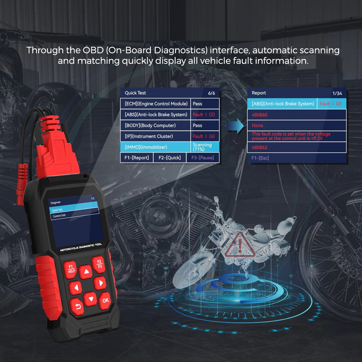
A diagnostic scan tool reads information from an electronic control system. It may display stored faults, current warnings, sensor information, and other operating data. The correct reader depends on the equipment being diagnosed. A reader designed for one vehicle or machine may not communicate with another system.
This is especially important when working with cars and motorcycles. Vehicle diagnostic trouble codes follow defined standards for supported onboard diagnostic systems. SAE J2012 defines standardized diagnostic trouble codes and also includes ranges reserved for manufacturer-specific use. A general-purpose reader may access common information but may not support every manufacturer-specific function.
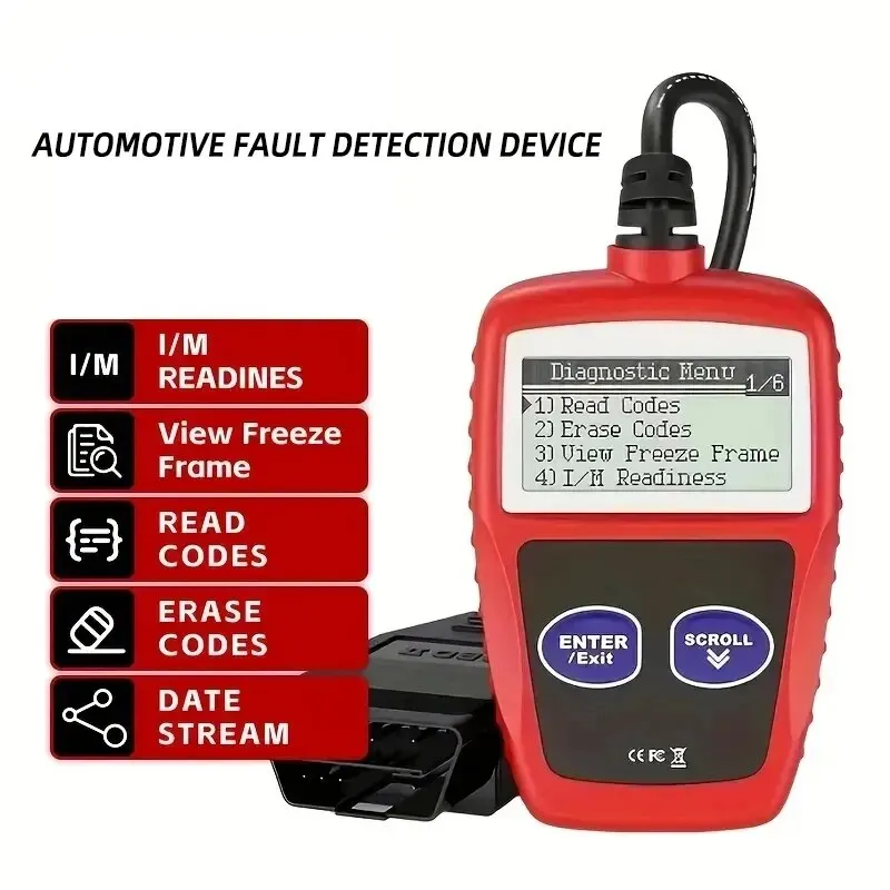
A vehicle code reader should not be confused with a general power-tool diagnostic device. Most cordless drills, saws, routers, and nailers use their own electronic control systems. Some have connected service platforms or internal diagnostic functions, but ordinary OBD-II scanners do not automatically read their faults.
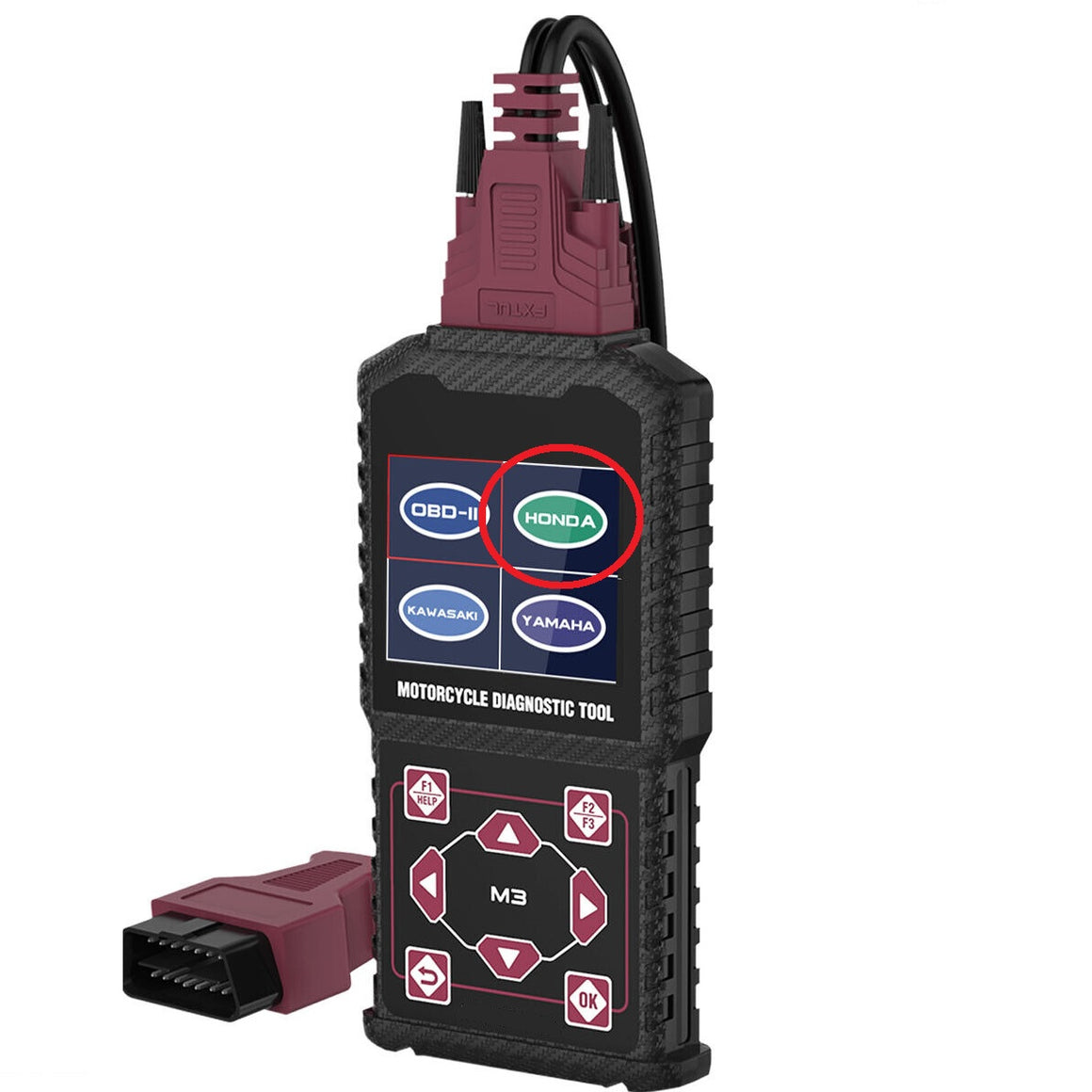
The diagnostic scanner examples shown in this guide are designed for vehicle or motorcycle diagnostic applications. Their appearance does not mean they are suitable for every power tool. Check the equipment manufacturer’s approved reader, connector, software, and communication protocol before buying or connecting a scanner.
Source: atvbikeco.com
Generic diagnostic reader
Can access supported standard information on compatible systems. Its available functions may be limited to basic codes and selected live data.
Manufacturer-specific scanner
May provide access to additional control modules, special tests, service functions, and brand-specific fault descriptions.
Connected tool application
May display supported tool information, service records, settings, or diagnostic feedback through a compatible phone or computer.
Professional diagnostic equipment
May provide deeper electrical measurements, control-system tests, and service functions when used by trained technicians.
What to Check Before Using a Diagnostic Scanner
Start by confirming the exact equipment model and the scanner’s supported applications. Check the connector type, communication protocol, software version, and any required adapter. For motorcycles, compatibility may depend on the manufacturer, model, production year, and control unit.
Read the connection instructions before plugging in the device. Some diagnostic procedures require a particular ignition state or power condition. Others require a stable battery supply. Connecting the wrong device or using an incorrect procedure may produce communication errors or unreliable information.
Equipment support
Confirm that the reader lists the exact make, model, and system you need to diagnose.
Connector and adapter
Check the required connector and adapter. A matching physical plug does not guarantee compatible communication.
Software support
Check whether the reader needs updated software, a subscription, or a supported mobile application.
Diagnostic functions
Confirm whether the device can read stored codes, display live data, run tests, or perform resets.
How to Use Diagnostic Data to Confirm a Repair
A repair is not complete just because the warning disappears. Diagnostic feedback should help confirm that the original problem has been corrected. The final check should include the warning status, the tool’s normal operation, and any measurements that the manufacturer’s service procedure requires.
Start by comparing the new information with the original record. If the tool stores an event history, check whether the original fault remains active or has returned. Some systems distinguish between active, pending, stored, or historical faults. These terms depend on the system, so follow its documentation.
Next, carry out the prescribed functional test. A drill should operate with the correct accessory and suitable material. A nailer should complete its approved operating checks. An engine-powered machine should complete the required diagnostic or running test under the correct conditions.
If the warning returns, do not keep clearing it. A recurring fault is useful diagnostic evidence. It may show that the first repair did not address the cause, that a connection remains unstable, or that another part is affected.
Source: atvbikeco.com
Compare before and after records
Check whether the original code, indicator, or abnormal reading remains present after the repair.
Check normal operating response
Confirm that the tool starts, runs, and stops as intended without abnormal noise, heat, vibration, or loss of power.
Repeat the relevant test
Use the same approved test conditions that caused the original problem, where safe and appropriate.
Record the repair
Document the fault, inspection results, replaced parts, service work, and final test outcome.
Why Clearing a Code Is Not the Same as Fixing a Fault
Clearing a code may remove a stored warning from the display or reset a controller’s fault memory. It does not repair damaged wiring, worn bearings, a weak battery, a blocked motor, or a faulty sensor.
Some systems also use stored information to help technicians understand an intermittent problem. Clearing it too early may remove useful evidence. Always record the original information and repair the cause before using an approved clearing procedure.
If the warning returns, treat it as an unresolved problem. Do not bypass a sensor, disable a protective circuit, or force the tool to run simply to remove the warning.
Record first
Save the original code and related information before performing a reset.
Repair the cause
Follow the correct diagnostic procedure and address the confirmed fault.
Clear only when permitted
Use the manufacturer’s reset or code-clearing method after the repair.
Common Diagnostic Mistakes and Important Limitations
Diagnostic feedback is useful, but poor interpretation can lead to unnecessary repairs. One common mistake is treating every warning as proof that a specific part has failed. Another is using a generic code list without checking whether it applies to the exact tool or control system.
A warning may also appear because of temporary operating conditions. A tool can stop because its temperature or load limit has been reached, even when no permanent component failure exists. The correct response is to identify the detected condition and follow the documented recovery procedure.
Electronic feedback also has limits. A controller can only report conditions that its sensors and software are designed to detect. A mechanical crack, worn bearing, loose guard, or damaged cord may not produce an electronic code. Physical inspection remains necessary.
Source: atvbikeco.com
Assuming all brands use the same codes
Avoid this because indicator colors, fault numbers, and reset procedures can differ between models.
Replacing parts based on one warning
Confirm the circuit, connections, operating conditions, and related components before replacing an expensive part.
Ignoring physical symptoms
A tool may have unsafe damage even when the electronic system shows no warning.
Using an incompatible scanner
An unsupported reader may show incomplete data, fail to connect, or miss manufacturer-specific information.
Resetting before recording
This may remove useful fault history and make an intermittent problem harder to diagnose.
Repeatedly restarting a faulty tool
Repeated attempts can increase heat, worsen damage, or defeat the purpose of a protective shutdown.
Ignoring maintenance alerts
A service indicator may identify a scheduled maintenance need before a more serious operating problem develops.
When a Tool Has No Fault Code
A tool can still have a serious fault without displaying a warning. Older tools may have no electronic monitoring system. Even advanced models may not have sensors for every mechanical or electrical problem.
Use physical inspection and approved functional checks when no code is available. Look for damaged cords, loose connections, unusual vibration, excessive heat, poor alignment, worn accessories, and damaged guards. If a fault affects safe operation, remove the tool from service even when its display looks normal.
Check external condition
Inspect the casing, handle, cord, plug, guards, switches, and accessories.
Compare operating behavior
Look for changes in sound, speed, power, heat, vibration, or movement.
Use approved testing
Arrange suitable electrical or mechanical tests when the fault cannot be confirmed through normal inspection.
Safety Rules and Professional Diagnostic Support
Safety must come before fault-code interpretation. A tool that shows an electrical, thermal, or mechanical warning may be unsafe to operate. Turn it off and isolate its power source before inspection, cleaning, or approved maintenance. For battery-powered tools, remove the battery when the manual requires it.
For pneumatic equipment, disconnect the air supply and release stored pressure according to the manufacturer’s instructions. Hydraulic tools may also hold pressure after the power source is removed. Never assume that a stopped tool has no stored energy.
OSHA guidance for portable and hand-held power tools emphasizes proper maintenance, pre-use inspection, correct operation, and removal of damaged equipment from service. In a U.S. workplace, employers and workers should follow the applicable safety rules and the tool manufacturer’s instructions.
Do not open sealed battery packs, bypass protective circuits, defeat safety switches, or test exposed live electrical parts unless you are trained and authorized to do so. Electrical repairs, control-board diagnosis, and internal battery work may require qualified service personnel.
Stop when there is smoke or a burning smell
Disconnect power if safe to do so, keep clear of the equipment, and arrange qualified inspection.
Remove damaged tools from service
Do not use tools with cracked housings, exposed wires, broken guards, damaged plugs, or unsafe switches.
Avoid swollen or leaking batteries
Do not charge, open, puncture, or continue using a damaged battery pack. Follow the manufacturer’s safety and disposal instructions.
Use qualified electrical technicians
Seek trained help for internal wiring, control boards, insulation tests, motor circuits, and other hazardous electrical work.
Use authorized service for critical faults
Contact the manufacturer or an approved repair center when a persistent sensor, electronic, or safety-system warning appears.
When Professional Repair Is the Better Choice
Professional service is the right choice when a fault returns after basic checks, when the tool enters a safety lockout, or when the manual directs the user to an authorized service center. This is especially important for high-power equipment, electronic control systems, and tools used in demanding workplace settings.
A qualified technician can use model-specific service information, suitable test equipment, and approved replacement parts. The technician can also check whether the repair restored the tool’s intended safety functions.
Repeated electronic faults
Arrange service when the same warning appears after approved checks and resets.
Electrical damage
Seek qualified inspection when there are signs of short circuits, damaged insulation, overheating, or unusual sparking.
Safety system failure
Stop using the equipment if a guard, brake, trigger lock, sensor, or other protective feature does not work.
Unclear diagnostic results
Use professional testing when the fault requires internal measurements or special diagnostic software.
Frequently Asked Questions
Q
Are tool fault codes the same across all manufacturers?
No. Most power tool manufacturers use their own diagnostic systems, indicator patterns, and fault descriptions. Even two tools from the same brand may use different warning systems. Always check the manual for the exact model and product version.
Vehicle diagnostic trouble codes have defined standards for supported onboard diagnostic systems, but manufacturer-specific codes and functions may still require compatible equipment.
Q
Can I keep using a tool when its fault indicator is flashing?
That depends on the exact warning. Some flashing indicators show low battery charge or a temporary operating condition. Others identify a serious fault or protective shutdown. Read the manual before continuing.
Stop using the tool if it shows signs of electrical damage, overheating, unsafe movement, smoke, a burning smell, or a critical warning. Never bypass a protective function to keep working.
Q
Will clearing a fault code repair the tool?
No. Clearing a code removes or resets diagnostic information. It does not repair the failed part or correct the condition that caused the warning.
Record the original fault, identify and repair the cause, and then follow the manufacturer’s approved reset procedure. If the warning returns, further diagnosis is needed.
Q
Why does my tool show an error even with a fully charged battery?
A full battery does not rule out every power-related problem. A weak battery can sometimes fail under heavy load even when its charge display looks normal. Dirty contacts, temperature limits, excessive current demand, and internal tool faults can also cause warnings.
Check battery compatibility, physical condition, contacts, and operating temperature. If the fault continues with an approved battery and charger, arrange service.
Q
Can a standard OBD2 scanner read every motorcycle or power tool fault?
No. An OBD2 scanner reads supported vehicle diagnostic systems. Motorcycle compatibility can depend on the brand, model, year, connector, adapter, and communication protocol.
Most ordinary cordless power tools do not use OBD2. They require their own manufacturer-supported diagnostic methods, connected applications, or service equipment. Confirm compatibility before buying or connecting a reader.
✦ Wrapping Up
Conclusion
Tool fault codes, warning lights, alarms, and diagnostic feedback help users understand why equipment is not working as expected. They can identify conditions such as low battery power, excessive heat, overload, blocked parts, sensor faults, and scheduled maintenance needs. However, these signals are starting points for diagnosis, not automatic proof that a particular component has failed.
A good diagnostic process begins with the exact model and its manual. Record the warning, check the operating conditions, inspect accessible components, and perform only approved tests. Use a compatible scanner when the equipment supports electronic fault reading, and never assume that vehicle diagnostic codes apply to ordinary power tools.
Always verify the repair before returning equipment to service. If a warning returns, the tool behaves abnormally, or the problem involves internal electrical or safety components, stop and seek qualified help. A careful diagnosis can prevent unnecessary part replacement, reduce downtime, and help keep the equipment safe.
💡 Key Takeaway
Before clearing any tool fault, record the exact code or indicator pattern, identify the model, consult its official manual, and check the safest likely causes. Repair the confirmed problem and perform an approved functional test before using the tool again.
Tubing cutter vs hacksaw: Compare speed, cut quality, cost and when to use each—get quick expert tips to pick the best tool for plumbing and DIY projects.
Not sure whether to pick a bar clamp vs pipe clamp? Compare strength, price, and uses to pick the right clamp for your workshop — quick, clear guidance.