Tool burrs are unwanted pieces of material that remain along a workpiece edge after cutting, drilling, milling, turning, or grinding. Good burr control starts with the right tool, cutting settings, and workholding. Proper deburring then removes leftover material without changing the part size, shape, or function.
In U.S. machine shops, metal fabrication plants, automotive factories, and woodworking facilities, a finished part must have more than the right shape. Its edges must also meet the required quality level. A small burr can affect assembly, damage nearby parts, cause a cut, or block a close fit. This makes burr control a key part of good production work.
A burr forms when a cutting tool pushes, bends, or tears material instead of removing it cleanly. The result may look like a thin flap, a rough ridge, a sharp point, or a small piece of metal. Its size and shape depend on the workpiece, cutting tool, tool wear, feed rate, and cutting direction. The same tool can also leave different burrs on different parts of one workpiece.
Deburring removes these unwanted edges. However, removing too much material can create a new problem. It may change a hole size, round an edge, reduce a mating surface, or affect a seal. The goal is not to make every edge look smooth. The goal is to produce the edge shape that the part needs. Research on burr control also shows why prevention and measurement matter as much as removal.
Source: indiamart.com
What Is a Tool Burr and Why Does Edge Quality Matter?
A burr is unwanted material that remains outside the intended shape of an external edge. It often forms during machining or metal forming. It may be thin and sharp or thick and difficult to remove. Some burrs are easy to see, while others need magnification.
Edge quality describes the shape, size, condition, and finish of a part’s edges. It includes more than the absence of sharp material. A finished edge may need a small chamfer, a rounded radius, or a controlled sharp edge. The correct condition depends on the part design and its job.
A burr can affect both safety and function. It may stop two parts from fitting together. It can also scratch a sealing face, block a small passage, or damage a wire during assembly. On moving parts, loose burr material may enter a bearing, valve, or other close-fitting area. These risks explain why edge inspection belongs in the quality plan.
Surface finish and edge quality are related, but they are not the same. A machined face may have a smooth finish while its edge still carries a sharp burr. A good surface roughness reading does not prove that the edge is free from unwanted material.
Source: indiamart.com
Assembly quality
Burrs can prevent parts from sitting flat or entering holes and slots. They may also change the clearance between mating parts.
Worker safety
Sharp metal edges can cut hands during handling, packing, and assembly. Small loose pieces can also become flying debris.
Part performance
A burr near a seal, bearing, valve, or fluid passage can affect fit and function. A loose burr may also contaminate a working system.
Dimensional control
Aggressive deburring can remove good material. This may create an oversized chamfer, a rounded corner, or an undersized feature.
Four Common Types of Machining Burrs
Burrs can be grouped by the way they form. Four common types are Poisson, rollover, tear, and cutoff burrs. These groups help explain the cause and guide the choice of a removal method. A single part can have more than one type.
Poisson burr
This burr forms when a cutting force compresses material and pushes it sideways. The material flows beyond the edge instead of leaving with the chip. It is linked to plastic deformation.
Rollover burr
This burr forms when material bends over the edge as the cutting tool exits. It often looks like a thin flap or curled lip. It is common in cutting and milling operations.
Tear burr
This burr forms when material tears or fractures instead of separating through a clean cut. It may have a rough and uneven shape. Material behavior and cutting conditions affect its size.
Cutoff burr
This burr remains where a part separates from stock during turning, sawing, or another cutoff process. It often appears near the final contact point.
Where Burrs Usually Appear
Burr location often gives a useful clue about its cause. Drilled holes may have burrs at the entrance or exit. Milled slots may have burrs along the sides or at the end of a tool path. Turned parts may have a raised lip where the cutting tool leaves the workpiece.
Punching and shearing can leave a rough edge on one side of a sheet. Grinding can also leave small raised areas when the wheel is worn or the work is unstable. Checking the burr location before choosing a removal method helps avoid unnecessary work.
Entrance burr
Forms where the cutting tool first contacts the workpiece.
Exit burr
Forms where the tool breaks through or leaves the material.
Side burr
Forms along a side edge due to lateral material flow.
Internal burr
Forms inside a hole, slot, or crossing passage where access may be limited.
How Burrs Form During Cutting and Machining
Burrs form when the cutting process causes material to bend, spread, or tear at an edge. A cutting tool creates force and heat as it moves through the workpiece. Most of the material should leave as a chip. However, the material near an edge may lose support and move in a different direction.
As a tool reaches the end of a cut, the remaining material may bend before it separates. This creates a rollover burr. In other cases, the tool compresses material and forces it sideways. A weak or damaged cutting edge can also tear the material and leave a rough ridge.
The workpiece material plays a major role. Soft and ductile metals can bend and stretch before breaking. This can create long, thin burrs. Hard or brittle materials may break in a less controlled way. Their edge damage can include chips and small fractures instead of a typical metal burr.
A review of machining research identifies material behavior, tool geometry, and cutting conditions as key parts of burr formation. A 2024 study of AISI 1045 steel planing also found that built-up edge and machine movement affected the measured burr results. This shows why one cutting speed or feed setting cannot be treated as a universal fix.
Source: indiamart.com
Workpiece material
Ductility, hardness, heat response, and material structure affect how the edge bends or breaks. Aluminum, stainless steel, mild steel, and cast materials may produce different burr shapes.
Cutting edge condition
A worn, chipped, or damaged tool may rub and tear the material. A built-up edge can also change the effective cutting geometry.
Tool geometry
Rake angle, clearance angle, cutting edge radius, and tool shape affect the way the chip separates from the workpiece.
Feed rate
Feed changes the chip thickness and the force placed on the edge. Excessive feed may increase deformation, while an unsuitable low feed may cause rubbing.
Cutting speed
Speed changes heat, friction, chip flow, and tool behavior. Its effect on burr size depends on the material and machine conditions.
Workpiece support
Poor support allows the edge to bend or move during cutting. A rigid fixture or suitable backing material can help control the exit edge.
Machine stability
Runout, vibration, tool deflection, and loose workholding can cause uneven cutting. These effects may create burrs that vary from one part to another.
Why Cutting Speed Does Not Have One Universal Effect
It is tempting to assume that higher cutting speed always creates smaller burrs. This is not a safe general rule. Speed can reduce friction in one process, but it can also increase heat and change material flow.
In a 2024 planing study on AISI 1045 steel, the researchers recorded different burr heights at different cutting speeds. A built-up edge affected the low-speed result, while machine dynamics affected the high-speed result. The study also found that burr volume and maximum burr height did not always respond in the same way.
These results apply to the tested setup, not every milling, drilling, or turning job. The useful lesson is to test a controlled change with the actual material, tool, and machine. Keep the settings that improve edge quality without causing heat damage, poor surface finish, or tool wear.
Do not change several settings at once
Change one main factor during a controlled trial. This helps show which change affects the burr.
Keep the material grade, tool condition, feed, speed, fixture, and burr inspection results with the process record.
Burrs on Composite Materials
Composite materials need extra care. Carbon fiber reinforced plastic can show frayed fibers, delamination, or damaged edges after drilling. These defects are not always the same as metal burrs. A metal scraper or aggressive brush may damage the fibers or coating.
Research on drilling carbon fiber composites discusses the need for suitable burr measurement and removal methods. The method should match the material structure, layer direction, and part requirements. Use the approved process for the specific composite rather than applying a metalworking method without validation.
Check for fiber damage
Inspect for loose fibers, layer separation, and cracks around the hole.
Use material-specific tools
Choose cutting and finishing tools approved for the composite and its surface protection.
How to Prevent Burrs Before Deburring
The best way to control burrs is to reduce their formation during machining. This can save time and reduce the risk of damage from later finishing work. Prevention also helps keep edge quality more consistent across a production run.
Start by checking the cutting tool. Its edge should be sharp and free from chips or unusual wear. Next, check the workpiece support and tool alignment. A stable setup helps the cutting edge remove material in a more controlled way.
The cutting path also matters. Plan where the tool enters and exits the material. If possible, direct the exit toward a supported or easy-to-finish area. This can reduce the effect of unsupported material at the end of a cut.
For drilling, a suitable backing plate can support the material as the drill breaks through. For milling, toolpath changes may help move the exit burr to an accessible edge. These methods need testing because material thickness, part shape, and tool direction affect the result.
Source: walmart.com
Use a sharp cutting tool
Replace or service tools when wear, chipping, or poor cutting becomes visible. Do not wait for severe edge damage.
Check alignment and runout
Verify that the tool and workpiece are properly aligned. Excessive runout can create uneven cutting forces and edge defects.
Improve workholding
Secure the workpiece with a suitable fixture. Support thin material near the cutting area where the process allows it.
Review feed and speed
Use settings suited to the material, tool, and machine. Validate changes through sample parts instead of relying on a general speed rule.
Plan the tool exit
Review the point where the cutter leaves the material. Consider a different path or suitable support to limit edge bending.
Maintain the machine
Check bearings, spindle condition, tool holders, and fixture stability. Repair vibration or movement that affects cutting.
A Practical Burr Prevention Checklist
Use this sequence before changing a production process. It keeps the checks simple and helps identify the cause of poor edge quality.
Step 1: Inspect the tool
Look for a chipped edge, wear, built-up material, or an unsuitable tool shape.
Step 2: Check the material
Confirm the grade, thickness, hardness, and condition of the workpiece.
Step 3: Check the setup
Confirm workholding, tool alignment, runout, and support near the cutting edge.
Step 4: Review the cutting path
Identify where the tool enters and exits. Look for a better-supported exit direction.
Step 5: Make a controlled trial
Change one suitable process factor and inspect a sample part.
Step 6: Record the result
Keep the settings and inspection results when the change meets the required edge condition.
Signs That Burr Prevention Is Working
A good process produces similar edges across several parts. Burrs should become smaller or easier to remove. The workpiece should also keep its required dimensions and surface finish.
Watch for changes during a long production run. A burr that grows over time may point to tool wear, heat, or a change in machine stability. Do not treat one clean sample as proof that the full process is under control.
Consistent edge shape
The same edge areas show similar burr size and appearance.
Stable dimensions
The part remains within its drawing limits after cutting and finishing.
Lower finishing effort
The remaining burr needs less removal without requiring more pressure or repeated passes.
How to Choose the Right Deburring Method
The right deburring method depends on the burr type, material, edge location, production volume, and required finish. A hand tool may work well on one open edge. It may be unsuitable for a small internal passage or a part with a tight size limit.
Mechanical deburring is common in general manufacturing. It uses tools or abrasive media to remove unwanted material. Other methods use heat, chemicals, electricity, or a high-pressure fluid stream. Each method has limits and needs suitable process controls.
Before selecting a method, ask three questions. Can the tool reach the burr? Can it remove the burr without changing the part? Can the result be checked in a repeatable way? A method that removes material quickly is not always the best choice.
Source: indiamart.com
Manual deburring
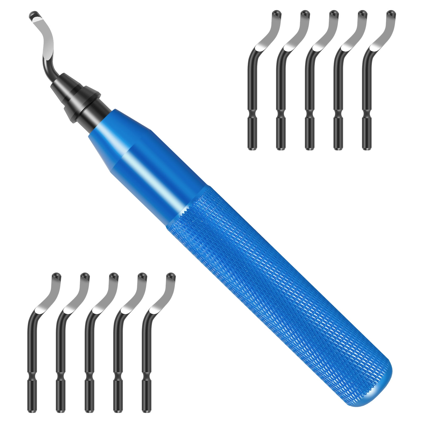
Files, scrapers, hand deburring tools, and small stones work well on accessible edges and low production volumes. They need operator skill and care. Excess pressure can create uneven chamfers or remove too much material.
Abrasive brushing
Abrasive brushes can remove light burrs and blend edges. They work well on accessible shapes. Brush pressure, speed, wear, and contact time must be controlled.
Abrasive belt and wheel finishing
These methods can remove larger burrs and finish open edges. They may also round corners or change surface dimensions if used too aggressively.
Vibratory and barrel finishing
Parts move with abrasive media inside a finishing machine. This can suit batches of small, robust parts. It may not reach deep holes or delicate features, and parts can strike each other.
CNC and robotic deburring
A programmed tool follows a planned edge path. This can improve repeatability in production. Tool wear, part variation, contact force, and programming still need control.
Electrochemical deburring
An electrical process removes material from selected areas of a suitable conductive workpiece. It can reach some difficult internal edges. It needs correct tooling, masking, electrolyte control, and trained operators.
Thermal energy deburring
A controlled heat process removes small burrs in suitable parts. It can reach several internal areas at once. It requires specialized equipment and careful control of material and part conditions.
Waterjet deburring
A directed fluid stream can remove suitable soft burrs without direct tool contact. It may help with some hard-to-reach areas. The part must tolerate the pressure and fluid exposure.
Match the Method to the Workpiece
A small aluminum part with an open edge may need only a hand deburring tool or a suitable brush. A large batch of similar steel parts may suit vibratory finishing if the parts can withstand contact with the media. A valve body with internal crossing holes may need a process designed for internal burr access.
A part with a sealing face needs extra care. Do not allow a brush or abrasive wheel to cross the sealing area unless the drawing and process permit it. A small change in edge shape may affect how the part seals or fits.
For precision parts, test the process on sample pieces first. Measure the edge before and after deburring. Check for removed material, surface damage, and changes to critical features. Use the results to set the production process.
For simple external edges
Use a controlled hand tool, file, or suitable abrasive brush.
For large batches
Consider vibratory or barrel finishing when the parts can tolerate the process.
For repeated precision work
Consider a CNC or force-controlled robotic process with a defined inspection plan.
For difficult internal burrs
Review electrochemical, thermal, waterjet, or abrasive-flow options with a qualified process specialist.
How to Deburr a Simple External Metal Edge
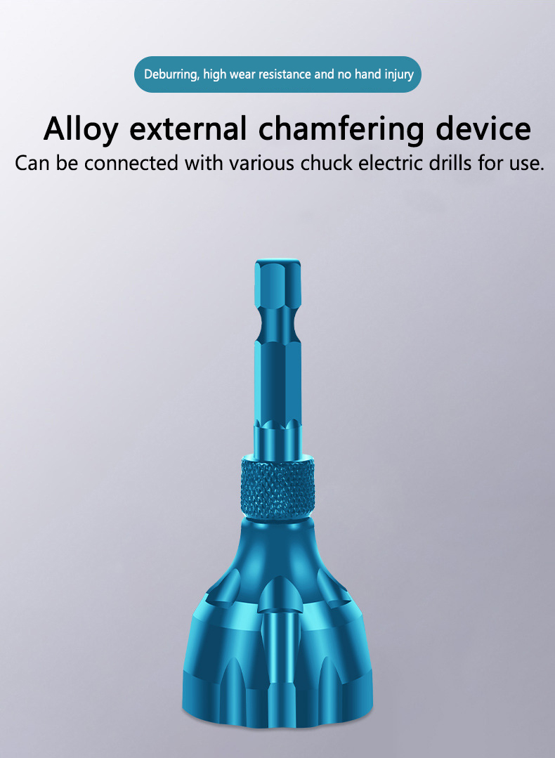
For an accessible external edge, a suitable hand deburring tool can remove a small burr. The part must be removed from the machine and held securely before the work begins. Follow the tool maker’s instructions and use the correct blade for the material.
Step 1: Clean and inspect
Remove loose chips and oil where the process allows. Identify the burr location and check the required edge shape.
Step 2: Secure the part
Use a stable fixture or suitable holding method. Keep hands away from sharp edges.
Step 3: Select the tool
Choose a blade, scraper, file, or brush suited to the material and edge geometry.
Step 4: Remove the burr
Use light, controlled contact. Follow the edge without digging into the parent material.
Step 5: Inspect the result
Check for loose material, remaining sharp points, excess rounding, and damage to nearby surfaces.
Step 6: Clean the part
Remove all chips and abrasive debris before final inspection or assembly.
How to Inspect and Specify Edge Quality
Good edge quality needs a clear acceptance rule. The rule should state what edge condition is allowed and how the result will be checked. A note such as remove all burrs may be too vague for a precision part unless the drawing or inspection plan explains what counts as acceptable.
Some parts need a completely clear edge. Others may allow a small burr or require a set chamfer or radius. A part may also need a sharp edge in one area and a rounded edge in another. The drawing should identify these differences.
ISO 13715:2017 covers the indication and dimensioning of edges of undefined shape in technical product documents. It provides a way to communicate permitted excess material and required material removal. It does not replace the need to define a suitable limit for the actual part and its function. The standard was reviewed and confirmed in 2024.
Source: indiamart.com
Visual inspection
Use suitable lighting and magnification to find raised material, rough edges, and loose fragments. Visual inspection is useful but may not show every small burr.
Burr height
Measure the height of the burr above the intended edge or reference surface when the inspection method supports it.
Burr thickness
Check the thickness of the raised material where it affects removal or function.
Edge radius or chamfer
Measure the finished edge shape when a radius or chamfer is required by the drawing.
Part dimensions
Check holes, slots, sealing faces, and mating surfaces after deburring. The process must not move them outside their permitted limits.
Cleanliness
Check that no loose chips, abrasive particles, or detached burr fragments remain on or inside the part.
Write Clear Edge Requirements on Drawings
A useful edge requirement tells the machinist and inspector what the finished edge should look like. It should also give a measurable limit when the edge affects fit, safety, or performance.
For example, a drawing may call for a specified chamfer size or edge radius. Another drawing may allow an undefined edge within a stated limit. These requirements are not interchangeable. A chamfer has a defined size and angle, while an undefined edge may allow a range of material removal.
Avoid using a general note when different edges have different jobs. A sealing edge, a handling edge, and a clearance edge may need different treatment. Mark the important edges clearly and link them to the right inspection method.
Define the edge condition
State whether the edge must be burr-free, chamfered, rounded, or allowed to retain a limited amount of excess material.
Set a measurable limit
Provide a dimension or suitable acceptance range where edge size affects function.
Identify critical edges
Mark sealing, mating, sliding, and safety-related edges separately when their needs differ.
Define inspection
State the measurement or visual inspection method and the inspection frequency when needed.
Burr Height Is Not the Only Useful Measurement
Burr height is easy to understand, but it does not describe the full shape of a burr. A narrow and tall burr may behave differently from a wide and thin one. The root thickness, length, direction, and volume may also matter.
For a simple production check, a defined maximum height may be enough. For process research or complex parts, additional measurements can provide a better picture. A 2024 machining study found that burr volume could show changes that maximum height did not clearly capture in its simulation work.
The measurement method should match the part and the acceptance rule. Optical inspection, suitable edge gauges, microscopy, or other metrology tools may be used. Do not compare measurements from different methods as if they were identical without checking their limits.
For simple parts
Use a clear visual check and an agreed edge limit when the part design allows it.
For close tolerances
Use suitable magnification and a repeatable measurement method.
For process development
Record burr height, thickness, length, and shape where these values help explain process changes.
For critical features
Confirm the final dimensions and functional fit after deburring.
Burr Troubleshooting, Common Mistakes, and Safety
A burr that keeps returning needs a process check, not just more deburring. Look at where it forms, when it appears, and whether its size changes during production. These details can point to tool wear, poor support, vibration, or an unsuitable cutting path.
A common mistake is to use more pressure when a burr is hard to remove. This may fold the burr over rather than cut it away. It can also damage the good edge beneath it. Choose a tool that reaches the burr root and use a controlled method.
Another mistake is to treat a shiny edge as proof of good quality. A polished edge can still have a raised lip or an oversized chamfer. Final inspection must check both the edge condition and the part dimensions.
Burrs grow during production
Possible causes include tool wear, a built-up edge, changing material conditions, and machine vibration. Inspect the tool and compare early and late production samples.
Burrs appear on only one side
Check the tool exit direction, workpiece support, cutting path, and fixture position. A change in material support may explain the one-sided defect.
Burrs remain after deburring
The method may not reach the burr root. Check the tool angle, blade condition, contact path, and access to the edge.
Edges become too rounded
The abrasive tool may be too aggressive or may stay in contact too long. Reduce unnecessary contact and inspect the edge radius.
Hole size changes after finishing
The deburring tool may be cutting into the hole wall. Use a controlled chamfering method and measure the hole after finishing.
Loose material remains inside the part
The cleaning method may not reach internal passages. Use a validated cleaning process and inspect the part before assembly.
Safety During Deburring Work
Deburring creates sharp chips, abrasive dust, sparks, and flying particles. Use eye and face protection suited to the process. Wear other protective equipment based on the material, tool, and workplace risk assessment.
Stop the machine before removing chips, changing a tool, or reaching near the cutting area. Follow the required energy isolation and lockout procedures before servicing or adjusting equipment. Never place a hand near a moving cutter or use a hand tool in place of required machine guarding.
OSHA machine-guarding guidance covers hazards from rotating parts, flying chips, and sparks. OSHA also states that point-of-operation hazards must be guarded where workers could be injured. Hand tools used to handle material do not replace required guards.
Grinding and powered brushing need extra care. Check the tool condition, guard, wheel rating, workholding, and approved operating speed. Keep loose clothing and unsuitable items away from rotating equipment. Follow the machine maker’s instructions and workplace safety rules.
Protect the eyes and face
Use suitable safety glasses and face protection where flying chips or abrasive particles are present.
Secure the workpiece
Use a proper fixture or holding method. Do not hold a small loose part by hand against a powered abrasive wheel.
Control machine energy
Stop and isolate equipment before servicing, changing tools, or clearing a hazardous jam.
Control dust and debris
Use suitable extraction and cleaning methods for the material. Follow the required controls for metal dust and other harmful particles.
Inspect the equipment
Check guards, abrasive tools, handles, and attachments before use. Remove damaged equipment from service.
When to Ask a Process or Quality Specialist
Get qualified help when a burr affects a pressure seal, safety-related feature, medical component, moving assembly, or critical internal passage. These parts may need a validated removal and inspection process.
A process specialist can review tool geometry, cutting settings, workholding, and finishing options. A quality specialist can help define measurable edge limits and select a suitable inspection method. This is especially useful when a part repeatedly fails inspection or deburring changes its dimensions.
Critical internal features
Seek specialist review when a burr is hidden inside a small hole or crossing passage.
Repeated quality failures
Review the machining process when burr size varies or defects return after finishing.
Material damage
Seek technical advice when deburring causes cracks, delamination, heat damage, or coating loss.
Unclear acceptance limits
Ask engineering and quality teams to define the permitted edge condition before production continues.
Research Scope and Important Next Questions
The research check for this guide was completed on November 7, 2026. The intended market is the United States, with a focus on machine shops, metal fabrication, and general manufacturing. Search queries covered machining burr formation, burr types, deburring methods, edge quality, and machine safety.
The reviewed technical pages included the CIRP review, Burrs: Analysis, Control and Removal, published in 2009; a 2024 Springer study of burr formation during AISI 1045 planing; the IEEE Technology Navigator deburring overview; ISO 13715:2017; and OSHA machine-guarding and hand-tool safety guidance. The CIRP review page was not fully accessible, so its available abstract was used only for its stated research scope. The 2024 study provides useful experimental detail, but its results are specific to the tested material and setup.
The reviewed material covers burr classification, formation, broad removal methods, drawing requirements, and machine safety. However, a general reader still needs a clear way to select a method, avoid over-removal, and check internal edges. This guide brings those decisions together rather than treating burr removal as a simple cosmetic task.
Search Console data, customer support records, and verified People Also Ask questions were not supplied. The questions below are therefore inferred next needs, not verified search demand. No site map was supplied, so parent and neighboring page relationships have not been assigned.
INFERRED NEXT NEED: What burr limit should a technical drawing specify?
Reader stage: Before production. Reviewed coverage: ISO 13715 explains edge indication and dimensioning, while the reviewed technical overview does not set a universal acceptance limit. Gap status: Partly answered. Reader benefit: A measurable drawing requirement reduces disputes between machining and inspection teams. Evidence: ISO 13715:2017. Priority: High. Placement: Edge inspection and specification section.
INFERRED NEXT NEED: How can drill exit burrs be reduced without changing hole size?
Reader stage: During machining. Reviewed coverage: Burr research explains exit formation and the value of workpiece support, but the reviewed pages do not provide one universal drilling procedure. Gap status: Shallow. Reader benefit: Better control of hole edges with less risk of oversizing. Evidence: Machining research on exit burr formation and backing support. Priority: High. Placement: Burr prevention section.
INFERRED NEXT NEED: How can an internal cross-hole burr be removed?
Reader stage: After machining. Reviewed coverage: The IEEE overview identifies fluid-based and electrochemical approaches, but does not select a process for every material and passage shape. Gap status: Shallow. Reader benefit: Helps readers avoid choosing a tool that cannot reach the burr root. Evidence: Technical deburring method classifications. Priority: Medium. Placement: Deburring method selection section.
INFERRED NEXT NEED: How can over-deburring be detected?
Reader stage: Final inspection. Reviewed coverage: ISO addresses edge indication, but the reviewed overview does not provide a full inspection sequence for detecting excess material removal. Gap status: Missing from the reviewed overview. Reader benefit: Helps protect hole size, sealing faces, and mating geometry. Evidence: Edge dimensioning principles and general metrology practice. Priority: High. Placement: Edge inspection section.
Evidence and Source Limitations
The CIRP review is a research overview of burr classification, measurement, control, and removal. Its available abstract supports the importance of burr prevention and measurement, but the full article could not be inspected during this research check.
The 2024 Springer paper studies a specific planing setup and AISI 1045 steel. Its results should not be used as fixed cutting recommendations for aluminum, stainless steel, drilling, or milling. The IEEE page provides a broad method overview, while ISO and OSHA provide guidance within their stated scopes.
The primary pages inspected included https://link.springer.com/article/10.1007/s00170-024-14150-1, https://technav.ieee.org/topic/deburring/, https://www.iso.org/standard/61328.html, https://www.osha.gov/etools/machine-guarding/introduction/general-requirements, and https://www.osha.gov/laws-regs/regulations/standardnumber/1926/1926.300. The CIRP review abstract was available at https://www.sciencedirect.com/science/article/pii/S0007850609001711.
DOCUMENTED
The cited research describes burr formation mechanisms, process factors, and deburring categories. ISO documents edge indication rules. OSHA documents applicable workplace safety requirements within its regulatory scope.
ANALYSIS
A controlled process should address prevention, removal, inspection, and dimensional checks together. This follows from the relationship between burr formation, edge geometry, and part function.
NOT ESTABLISHED
No universal feed rate, cutting speed, burr height, or deburring tool is suitable for every material and machining process. No hands-on product testing was conducted for this guide.
Frequently Asked Questions
Q
What causes burrs to form during machining?
Burrs form when workpiece material bends, spreads, or tears instead of separating cleanly during cutting. Common causes include worn tools, unsuitable cutting settings, poor workholding, excessive deformation, and machine vibration.
Material properties also matter. Ductile metals may form long rollover burrs, while brittle materials may show rough fractures or chips.
Q
Are all machining burrs required to be removed?
Not every edge needs the same treatment. The drawing and part function should define the required edge condition. Some parts need a burr-free edge, while others may allow a controlled edge condition or require a specific chamfer or radius.
A burr that can interfere with assembly, safety, sealing, or movement should not be ignored. Follow the approved drawing and inspection requirements.
Q
What is the difference between deburring and chamfering?
Deburring removes unwanted material that extends beyond the intended edge. Chamfering creates a defined angled surface between two edges or faces.
A chamfer can remove a burr, but the two operations are not identical. A part may need a small chamfer after the burr is removed, or it may need only a burr-free edge without a defined chamfer.
Q
How can I reduce burrs when drilling metal?
Start with a sharp drill, correct alignment, stable workholding, and settings suited to the material. A suitable backing plate can support the workpiece as the drill exits.
Review the breakthrough stage and inspect both sides of a sample hole. A controlled finishing tool may help, but it should not enlarge the hole beyond its required size.
Q
Which deburring method is best for internal burrs?
The best method depends on the passage shape, material, burr size, and access. Special internal deburring tools may work for accessible holes. Electrochemical, thermal, abrasive-flow, or suitable fluid-based methods may help with harder-to-reach areas.
Do not choose a process based on access alone. Confirm that it will not damage the workpiece, coating, or nearby features. For critical internal passages, use a validated process and inspection method.
✦ Wrapping Up
Conclusion
Tool burr formation is a normal risk in cutting, drilling, milling, turning, and other machining work. However, poor burr control can affect safety, assembly, dimensions, and part performance. The best approach starts with understanding why the burr forms and where it appears.
Good tools, stable workholding, suitable cutting settings, and careful toolpath planning can reduce burrs before they reach the finishing stage. When burrs remain, select a removal method that suits the material, edge location, and required geometry. Manual tools may work for simple edges, while complex internal features may need a specialized process.
The final check matters as much as the removal step. Inspect the edge, measure critical dimensions, and confirm that no unwanted material or finishing damage remains. A clean edge should meet the part requirement, not just look smooth.
💡 Key Takeaway
Before the next production run, inspect the cutting tool, workpiece support, and tool exit path. Make a sample part, measure its burr and finished edge, and record a clear acceptance limit. Use the least aggressive deburring method that reliably meets that limit without changing the part’s required dimensions.