Tool parts wear patterns reveal how components have been damaged and can help identify the cause before complete failure occurs. Inspect the shape, location, depth, and direction of wear. Compare the damage with operating symptoms, nearby parts, and manufacturer limits before deciding to repair or replace anything.
In American garages, woodworking shops, construction sites, and industrial maintenance rooms, tools face many types of stress. A drill may run for hours. A table saw may cut dense hardwood. An air compressor may start and stop throughout the day. Each task places different loads on the parts inside the tool. Over time, these forces leave marks that can help explain what went wrong.
Tool Parts Wear Patterns and Failure-Signature Diagnosis is the process of reading those marks. A scratched gear, worn bearing, cracked housing, or uneven carbon brush can reveal useful details about the way a tool has been used. The damage may also point to poor lubrication, dust, excess heat, loose fits, vibration, or overload.
The key is to look beyond the damaged part. A worn bearing may be the result of a failed seal. A damaged gear may point to poor alignment. Uneven brush wear may indicate a problem with the motor or commutator. Replacing the visible damaged part without checking nearby components can allow the same failure to return.
A sound diagnosis uses three forms of evidence: the visible damage, the tool’s operating history, and measured component condition. This guide explains how to inspect common wear patterns, connect them to likely causes, and make a safer repair decision. It does not assume that every tool follows the same wear limit or repair method.
Understanding Tool Parts Wear Patterns and Failure Signatures
A wear pattern is the visible change on a part after contact, movement, heat, or stress. It may appear as a smooth surface, a scratch, a dent, a crack, or a missing piece of material. The pattern often reflects the type of force that acted on the part.
A failure signature is a group of signs that helps describe a specific damage process. It may include the shape of the mark, its location, its direction, and nearby changes. A single mark can be unclear. Several matching signs often provide a stronger clue.
For example, a bearing with rough raceways may also show dark grease, metal dust, and heat marks. These signs support an investigation into lubrication and contamination. They do not prove one cause by themselves. The bearing fit, load, sealing, and service history still need review.
Wear
Wear is the gradual loss or change of material caused by contact, friction, or other repeated action.
Damage
Damage is a harmful change such as a crack, dent, chip, burn, or broken section.
Failure
Failure occurs when a part can no longer perform its required job within safe operating limits.
Failure signature
A recognizable group of physical signs that helps classify the damage and guide further checks.
Normal Wear Versus Early Failure
Normal wear develops as a part performs its intended job. A cutting edge becomes dull. A carbon brush becomes shorter. A sliding surface may develop a smooth contact mark. These changes do not always mean that a part has failed.
Early failure is different. It may show unusual wear in one area, rapid material loss, rough contact, cracks, or damage that appears before the expected service interval. A new noise or sudden rise in heat can support the concern.
The best comparison is a known-good part of the same type and model. If that is not available, use the maker’s service limits and inspection guidance. Never assume that a smooth or shiny surface is always healthy.
Why the Location of Wear Matters
The location of damage can be as useful as its appearance. Wear on one edge may point to poor alignment. Marks near a shaft shoulder may suggest a fit or contact issue. Damage across an entire surface may point to general contamination or a broader operating problem.
Look at both sides of a contact pair. A damaged gear tooth may have transferred material to its mating tooth. A worn shaft may also have damaged the bearing bore. The two parts should be examined together whenever the design allows it.
Safety and Preparation Before Inspecting Tool Parts
Safe inspection begins before the tool is opened. A damaged tool can still hold electrical, mechanical, pneumatic, or spring energy. Removing a cover without controlling that energy can cause serious injury.
For a corded tool, unplug it and keep the plug under control. For a cordless tool, remove the battery. Disconnect air hoses from pneumatic tools and follow the maker’s steps for releasing trapped pressure. Machines with hydraulic systems or large springs may need trained service staff.
Wait for hot parts to cool. Secure the tool on a stable work surface. Wear eye protection when dirt, metal pieces, or springs may move. Use suitable gloves for handling sharp parts, but never wear gloves near exposed rotating machinery.
Read the service instructions
Check the correct model manual for disassembly steps, service limits, torque values, approved lubricants, and replacement parts.
Control stored energy
Remove batteries, unplug cords, disconnect air supplies, and follow the correct procedure for springs, capacitors, and other stored energy.
Prepare the work area
Use good lighting, a clean bench, suitable containers, and a safe place for small parts.
Record the original condition
Take clear photos before cleaning or removing parts. Note noise, heat, vibration, smell, and any recent change in performance.
U.S. Workplace Safety Requirements
OSHA provides specific rules for portable powered tools. Under 29 CFR 1910.243(a)(4), cracked saws must be removed from service. The same regulation includes guarding and operating requirements for several types of portable tools.
OSHA 29 CFR 1910.334 also addresses visual inspection of portable cord-and-plug equipment. Damaged equipment that may expose an employee to injury must be removed from service until the needed repairs and tests have been completed.
These rules do not replace the manufacturer’s service instructions. They also do not make an untrained person qualified to repair electrical or mechanical equipment. Follow the rules that apply to the workplace and tool type.
Tools Needed for Inspection
A basic inspection may need a bright work light, a soft brush, a clean cloth, a magnifier, and a camera. A parts tray helps keep small washers, clips, screws, and springs in order.
More detailed work may need a digital caliper, micrometer, dial indicator, feeler gauge, or suitable test meter. Use each tool only within its rating and your level of training. A measurement is useful only when it is taken at the correct point and compared with a valid limit.
A Step-by-Step Method for Diagnosing Wear Patterns
A repeatable inspection method helps prevent missed clues. Start with the operating problem, then examine the parts that could produce it. Keep the original damage in view until photos and notes are complete.
Step 1: Record the symptoms
Write down when the fault occurs. Note whether it appears during startup, under load, at high speed, or after the tool becomes warm. Record unusual sounds, smells, vibration, and loss of power.
Step 2: Check the outside
Look for cracks, loose fasteners, missing guards, damaged cords, leaking grease, blocked vents, and signs of impact. Do not run a damaged tool to confirm a suspected fault.
Step 3: Open the tool only when permitted
Follow the service manual. Mark wire positions and part direction. Photograph each stage. Do not force covers, gears, bearings, or clips from their seats.
Step 4: Clean without hiding evidence
Remove loose dirt with a suitable brush or cloth. Photograph unusual deposits before cleaning. Do not use a harsh solvent that may damage seals, plastic, insulation, or lubrication.
Step 5: Inspect each component
Check contact faces, edges, holes, teeth, raceways, shafts, seals, and electrical parts. Record the location and direction of each mark.
Step 6: Measure the affected areas
Compare dimensions, clearance, runout, and free movement with the maker’s limits. Do not create a repair limit from a guess.
Step 7: Check nearby parts
Inspect the parts that touch, support, drive, or protect the damaged component. Look for a shared cause such as poor alignment, excess load, or contamination.
Step 8: Decide on the next action
Classify the damage, confirm the cause as far as the evidence allows, and choose cleaning, adjustment, approved repair, part replacement, or specialist inspection.
How to Record a Useful Wear Pattern
A useful record describes the damage without guessing at its cause. Write down the part name, tool model, service history, and location of the mark. Add the length, width, or depth when a suitable measurement is available.
For example, record that a gear tooth has a rough band along one side and visible metal transfer. Do not write that poor lubrication caused the damage until the lubricant and contact conditions have been checked.
Use the same light and camera angle for later inspections when possible. This helps show whether a mark has grown or whether the condition has changed after service.
Common Wear Patterns and What They Can Reveal
Different wear patterns often point to different damage processes. SKF’s published bearing damage guidance describes several forms of wear, corrosion, fatigue, electrical erosion, and deformation. ISO 15243 also provides a classification system for rolling bearing damage.
These classifications are useful for bearings, but they should not be applied blindly to every tool part. A plastic gear, a steel shaft, and a carbon brush have different materials and working conditions. Use the pattern as a starting clue, then check the component design.
Abrasive wear
Fine scratches, grooves, dull surfaces, or polished contact areas can point to hard particles between moving surfaces. Dust, metal fragments, poor sealing, and dirty lubricant are possible causes. Check the seal, lubricant, and cleaning process.
Adhesive wear and scuffing
Smeared metal, rough torn patches, and material transfer may point to sliding contact with a weak lubricant film. Excess heat, poor lubrication, high friction, and unsuitable load conditions need investigation.
Pitting and spalling
Small pits or larger flakes missing from a contact surface may indicate fatigue damage. Repeated stress, overload, poor lubrication, or contamination can contribute. Check the load and the condition of the mating parts.
Corrosion
Rust, dark stains, and surface pits can indicate contact with moisture or aggressive chemicals. Check storage, seals, cleaning fluids, and the work environment.
Fretting wear
Small reddish or dark marks near a fitted joint can result from repeated tiny movements. Loose fits, vibration, and poor support may contribute. Check the shaft, housing, and mounting surfaces.
Indentation and brinelling
Dents or small depressions may result from impact, excess load, rough handling, or trapped debris. Check how the part was installed and whether force passed through the wrong surface.
Electrical erosion
Tiny craters, gray marks, or a repeated washboard pattern on bearing surfaces may point to electrical current passing through the bearing. A qualified electrical investigation may be needed.
Cracking and fracture
Visible cracks, broken teeth, and missing sections can indicate overload, impact, fatigue, or stress concentration. Stop using the tool and assess the part and its supporting structure.
Thermal damage
Discoloration, melted plastic, damaged insulation, and hardened or burnt lubricant can point to excess heat. Check friction, load, cooling, ventilation, and electrical faults.
Abrasive Wear: Scratches and Grooves
Abrasive wear occurs when hard particles or rough contact surfaces remove material. A gear tooth may show long scratches along the direction of sliding. A bearing raceway may look dull or polished. Very fine particles can sometimes create a smooth, shiny surface instead of obvious scratches.
SKF explains that abrasive particles can enter through poor seals or come from wear inside the machine. This means the damaged part may not be the only problem. Inspect the lubricant, filter, seal, and nearby parts for signs of contamination.
Do not polish away deep scratches without checking the part’s size and surface finish. Material loss can change the fit and load distribution.
Adhesive Wear: Smearing and Metal Transfer
Adhesive wear can occur when moving surfaces make strong contact instead of remaining separated by a suitable lubricant film. Small areas may become shiny, then develop rough patches or smeared material. Severe gear scuffing can leave torn surfaces and heat marks.
Check lubricant type, amount, condition, and delivery. Also inspect the load, speed, alignment, and contact pattern. Adding more grease without checking the cause may not solve the fault.
Fatigue Damage: Pitting and Spalling
Fatigue damage develops under repeated stress. A bearing raceway may develop small pits that grow into larger areas of missing metal. Gear teeth may show small surface pits or larger flakes.
The damage can result from repeated load cycles, poor lubrication, contamination, or an overload event. Compare the damage with the contact zone and operating history. A cracked or heavily spalled load-bearing part should not return to service without an approved repair decision.
Corrosion and Fretting
Moisture corrosion often leaves rust or pits on exposed steel. It can affect parts during storage as well as operation. Check whether water entered through a damaged seal or formed through condensation.
Fretting is different. It occurs when two loaded surfaces move slightly against each other again and again. It may leave dark or reddish deposits around a bearing seat, shaft, or fitted joint. Loose fits and vibration are possible causes.
Electrical Erosion and Heat Marks
Electrical erosion can occur when unwanted current passes through a bearing. SKF describes small craters and, in later stages, repeated surface marks that may resemble a washboard. A dull gray surface can also be confused with other damage, so magnification and further checks may be needed.
Heat marks can have several causes. Friction, overload, poor cooling, and electrical faults can all raise temperature. Color alone cannot confirm the cause. Inspect the affected material, nearby parts, lubricant, and electrical system.
Diagnosing Wear in Common Tool Components
Each component has its own failure signatures. A good inspection links the visible mark to the part’s job. It also checks whether another part has caused the damage.
Bearings
Look for rough rotation, pitting, rust, discoloration, dents, and damage to the cage or seals. Check shaft and housing fits as well as lubricant condition. Do not reuse a bearing with serious damage or an uncertain fit.
Gears
Inspect tooth faces for scratches, pits, chipped edges, cracks, and smeared metal. Check the mating gear, backlash, shaft alignment, and lubrication.
Shafts
Look for scoring, worn journals, bent sections, damaged keyways, and marks near shoulders. Measure the relevant diameter and runout when the service manual provides limits.
Carbon brushes
Check brush length, contact face, free movement in the holder, spring action, and lead condition. Compare the remaining length with the tool maker’s service limit.
Commutators
Look for deep grooves, uneven surfaces, dark burns, metal transfer, and abnormal wear. Excessive sparking or brush damage may point to a wider motor fault.
Seals and O-rings
Check for cuts, hardening, swelling, flattening, cracks, and loss of shape. Confirm that the seal material matches the lubricant and operating environment.
Cutting edges and holders
Inspect blades, bits, cutters, and holders for dull edges, chips, cracks, uneven wear, and loose fits. Replace damaged cutting parts when sharpening or approved repair cannot restore safe use.
Housing and handles
Look for cracks around screws, bearing seats, mounting points, and handle joints. A damaged housing can affect alignment, protection, and operator control.
Bearing Wear Diagnosis
A bearing supports a rotating shaft and helps reduce friction. Common warning signs include grinding noise, rough movement, excess heat, vibration, and unusual movement at the shaft. These symptoms can also come from other parts, so inspect the full assembly.
Check the raceways, rolling elements, cage, and seals. Look for wear on the inner and outer rings. Also check the shaft seat and housing bore. A new bearing may fail early if the fit, alignment, or load remains wrong.
A bearing that has seized, cracked, or lost a major section of its rolling surface needs specialist review or replacement according to the machine maker’s instructions.
Gear Wear Diagnosis
Gears transfer motion and force between shafts. Their teeth must make the correct contact under load. Poor alignment, contamination, overload, and weak lubrication can change the tooth surface.
Inspect the full tooth face instead of one small area. A narrow worn band may point to uneven contact. Long scratches may point to abrasive particles. Pits may suggest fatigue, while rough torn areas may indicate scuffing.
The public description of ISO 10825-1:2022 explains that gear wear standards provide a shared way to name and describe damage. It also makes clear that damage appearance alone does not establish one cause or prescribe one repair.
Carbon Brush and Commutator Wear Diagnosis
Carbon brushes carry current between stationary and moving parts in certain electric motors. Some brush wear is expected. The key is to check whether the wear is even and within the tool maker’s limits.
Uneven brush faces, chipped edges, heavy dust, deep commutator grooves, and strong sparking need attention. Helwig Carbon’s brush guidance identifies brush-face condition as a useful sign of brush performance and describes several common brush and commutator problems.
Check brush movement, spring pressure, holder condition, and commutator surface. Do not fit a random carbon brush based only on its size. Brush grade, shape, and electrical properties must match the motor design.
Shaft, Seal, and Housing Wear Diagnosis
Shaft wear often appears where a bearing, seal, gear, or coupling makes contact. A worn journal may allow unwanted movement. A damaged keyway may reduce the ability to transfer torque. A bent shaft can cause vibration and uneven bearing loads.
Seal damage can allow dust, water, or lubricant to pass through. Look for hardened edges, tears, swelling, and worn contact bands. Check the shaft surface where the seal runs, because a damaged shaft can quickly wear a new seal.
A cracked housing needs careful assessment. The crack may affect the bearing seat, alignment, guard support, or handle strength. Do not cover it with glue or an unapproved patch and return the tool to use.
Measuring Wear Before Choosing a Repair
Measurements help turn a visual clue into a better repair decision. A part may look acceptable but be outside its allowed size. Another part may look rough yet remain within a maker’s service limit. The correct comparison depends on the tool and component.
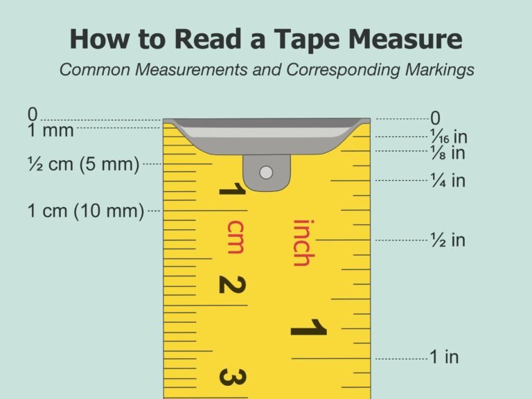
Digital caliper
Use it for suitable outside dimensions, inside dimensions, and part lengths. Check that the jaws sit squarely on the surfaces.
Micrometer
Use a suitable micrometer when a more precise shaft or part diameter measurement is needed. Follow the tool’s measurement range and method.
Dial indicator
Use it to check runout, movement, or alignment when the service procedure calls for it. Secure the work before taking readings.
Feeler gauge
Use it to check suitable gaps and clearances. Do not force a blade into a tight space.
Magnifier
Use it to inspect small cracks, pits, burrs, and surface marks that may be hard to see with the naked eye.
Compare Measurements With the Correct Limit
Always use the service specification for the exact tool model and component. A general measurement from another model may not apply. Different materials and designs can have different wear limits.
For example, a shaft may need to meet a specified diameter and runout limit. A bearing may need to meet a specified clearance or fit. A carbon brush may need a minimum remaining length. Use the maker’s stated values rather than a guessed number.
Take more than one reading when the surface may be worn unevenly. Compare readings from several points and record where each one was taken. A single reading can miss a worn area.
Use a Simple Wear Record
A simple inspection record can include the part name, original size if known, current measurement, wear location, visible damage, and service limit. Add the date and tool operating history when available.
This record helps show whether the wear is stable or getting worse. It can also help a repair shop compare a failed part with a replacement. Keep photos with the measurements.
Finding the Root Cause Behind a Failure Signature
The damaged part is not always the part that caused the problem. A bearing may fail because a seal let dust enter. A gear may wear because a shaft is bent. A motor may overheat because a fan path is blocked.
Root cause diagnosis means checking the full chain of events. Look at the damaged part, the parts that touch it, the way the tool was used, and the conditions around it. This is more useful than replacing parts one at a time without a clear reason.
Poor lubrication
Look for dry contact areas, burnt grease, metal transfer, heat, and rough surfaces. Check lubricant type, amount, condition, and service interval.
Dust and contamination
Look for grit, dirty lubricant, blocked filters, damaged seals, and particles trapped in contact areas. Find how the material entered the tool.
Misalignment
Look for uneven tooth contact, one-sided bearing wear, shaft runout, and repeated damage near one edge. Check mounting surfaces and supports.
Overload
Look for dents, broken teeth, cracks, bent parts, and heavy contact damage. Review the tool’s rated capacity and how the operator used it.
Excess vibration
Look for loose fasteners, fretting marks, worn supports, and unusual bearing damage. Check balance, mounting, and connected equipment.
Heat and poor cooling
Look for burnt lubricant, darkened parts, damaged insulation, and blocked air paths. Check the fan, vents, load, and duty cycle.
Incorrect installation
Look for damaged threads, dents, uneven seating, bent retainers, and marks from tools used during assembly. Check the correct installation procedure.
Check Both the Failed Part and Its Mating Part
A gear and its mating gear should be checked as a pair. A shaft and bearing should be checked together. A seal and its running surface should also be inspected as a pair.
If one part is replaced while the other remains damaged, the new part may wear quickly. This can make a repair seem successful at first, then lead to another failure.
The same rule applies to cutting parts. A damaged blade holder, loose chuck, or worn arbor can affect the new blade or cutter. Check the full connection before returning the tool to service.
Use Symptoms to Support the Physical Evidence
Noise can help narrow the search, but it cannot prove a single failure mode. A grinding sound may come from a bearing, gear, or damaged cutting part. A high-pitched sound may come from friction, airflow, or another rotating component.
Vibration can point to imbalance, poor alignment, a damaged bearing, or loose mounting. Heat can point to excess friction, overload, or a cooling problem. Compare these signs with the physical marks before reaching a conclusion.
If the symptoms and visible damage do not match, keep investigating. Do not force a diagnosis just because one part looks worn.
When to Repair, Replace, or Seek Professional Help
The correct action depends on the part’s job, the damage, the maker’s limits, and the skill needed for repair. A dull approved cutting edge may be sharpened. A cracked saw blade must be removed from service. A damaged bearing or gear may need replacement rather than surface repair.
A repair is suitable only when the maker permits it and the part can be restored to the required condition. Do not grind, weld, bend, glue, or reshape a safety-critical part unless an approved procedure allows it.
Cleaning or adjustment
This may be suitable when dirt, a loose approved adjustment, or a blocked vent is the only confirmed problem and no damaged part remains.
Approved repair
Use this option when the manufacturer provides a repair method and the required tools, skills, and checks are available.
Component replacement
Replace a part when it is cracked, broken, outside its service limit, badly worn, or not approved for repair.
Professional inspection
Seek qualified help for electrical faults, damaged motor windings, major bearing failures, uncertain cracks, pressure systems, and complex alignment problems.
Signs That a Tool Must Stay Out of Service
Remove a tool from service when a damaged part could affect safe operation. Examples include a cracked saw blade, failed guard, damaged power cord, broken handle, loose accessory holder, or serious structural crack.
Do not test a tool by running it with an exposed gear train or removed safety guard. A tool that starts and runs is not automatically safe. It must also meet the required mechanical and electrical conditions.
After repair, inspect the tool again. Check that fasteners, guards, covers, switches, and safety devices are installed as required. Complete any tests specified by the manufacturer or workplace procedure.
Why Replacing Only the Visible Damaged Part Can Fail
A damaged component may be the final result of a problem elsewhere. A new bearing will not solve a bent shaft. A new gear may fail if the housing keeps it out of alignment. A new brush may wear quickly if the commutator remains damaged.
Before ordering a replacement, identify the parts that support, drive, lubricate, or protect the damaged component. Check their condition and correct any confirmed cause that could damage the new part.
Common Mistakes During Wear Pattern Diagnosis
Wear diagnosis can go wrong when the inspection focuses only on appearance. A polished surface may be normal in one design and harmful in another. A dark stain may come from heat, oil, corrosion, or normal material changes.
Good diagnosis depends on evidence. Record the condition before cleaning, measure the parts, check the mating surfaces, and compare the findings with the correct service information.
Treating every mark as failure
Some contact marks are expected. Check the part’s normal operating pattern and service limit before replacing it.
Assuming one mark proves one cause
Different damage processes can look alike. Use location, texture, measurements, operating history, and nearby parts to support the diagnosis.
Cleaning before taking photos
Cleaning can remove useful evidence such as metal dust, lubricant color, and wear debris. Record the original condition first.
Ignoring the mating component
A damaged contact partner can quickly damage a new replacement part. Inspect both sides of the contact.
Using the wrong replacement part
A part that looks similar may have a different size, material, rating, or fit. Confirm the exact model and approved part number.
Guessing at wear limits
Do not use a general internet value as a substitute for the manufacturer’s specification. Different designs may have different limits.
Returning a damaged tool to work
Do not use a tool with an unresolved safety defect. Tag it and keep it out of service until an approved repair and required checks are complete.
Do Not Confuse Surface Wear With Structural Damage
A shallow scratch may be a surface issue. A crack near a bearing seat or mounting point can affect the strength of the whole part. The two conditions need different responses.
When a crack is suspected, do not sand the area and assume the problem is gone. Some cracks need specialist inspection methods. Replace the part when the maker requires replacement or when its safe condition cannot be confirmed.
Do Not Use Unapproved Lubricants or Solvents
The wrong lubricant can affect seals, plastics, friction surfaces, and bearing performance. A strong solvent may also remove protective films or damage insulation.
Use only the lubricant and cleaning method listed for the exact tool. More lubricant is not always better. Excess grease can create heat, leakage, or other problems in some designs.
Building a Better Tool Wear Inspection Routine
A simple inspection routine can catch changes before they cause a major breakdown. The best routine matches the tool’s use, risk, and maker’s service instructions. A heavily used shop machine may need more frequent checks than a tool used for occasional home repairs.
Keep a record of unusual noise, heat, vibration, part replacement, and measured wear. This history makes it easier to spot repeat problems and see whether a repair has worked.
Before each use
Check the body, handle, cord or battery, switch, guard, accessory, and visible signs of damage.
During scheduled maintenance
Inspect wear parts, lubrication, air paths, fasteners, seals, and the condition of moving components according to the service manual.
After unusual operation
Inspect the tool after a hard impact, jam, overheating event, sudden vibration, or unexpected loss of power.
After repair
Check the assembly, part fit, fasteners, guards, switches, and required test results before returning the tool to service.
Keep a Simple Maintenance History
Record the date, tool model, operating hours when known, parts inspected, measurements, and repairs. Add photos when a part shows an unusual pattern.
A maintenance record can reveal repeat failures. For example, if several bearings fail near the same interval, check the operating load, seal design, fit, and lubrication process. The repeated pattern may point to a shared cause.
Use the record to plan inspections, not to replace parts on an arbitrary schedule. Follow the service interval and wear limits set by the manufacturer.
Frequently Asked Questions
Q
What are the most common tool parts wear patterns?
Common patterns include scratches, grooves, polishing, smearing, pitting, spalling, rust, dents, cracks, and uneven contact marks. Each pattern can point to a different type of stress or damage.
Abrasive wear often leaves scratches. Adhesive wear can leave transferred or smeared metal. Fatigue may cause pits or missing surface material. Corrosion often leaves rust or pits. The component type and operating conditions determine how these signs should be interpreted.
Q
How can I tell whether a tool part is worn or defective?
Compare the part with a new matching part or the manufacturer’s service specification. Check its dimensions, surface condition, fit, movement, and function.
Normal wear is usually within the allowed service range. A defective part may show cracks, severe material loss, excessive clearance, unusual heat damage, or another condition that affects safe operation. When the limit is unclear, seek qualified inspection.
Q
Can wear patterns identify the exact cause of tool failure?
Wear patterns can narrow the possible causes, but one mark rarely proves an exact cause. Similar damage can result from poor lubrication, overload, contamination, misalignment, or incorrect installation.
For a stronger diagnosis, inspect the damaged part, its mating components, operating symptoms, measurements, and service history together. Complex failures may require specialist testing.
Q
Which tools are best for measuring component wear?
Digital calipers, micrometers, dial indicators, feeler gauges, and magnifiers are useful for many inspections. Each tool measures a different feature.
The correct instrument depends on the part and required accuracy. Always compare the reading with the specification for the exact tool model. Visual inspection alone is not enough when a precise fit or clearance matters.
Q
Should I replace a part when I see unusual wear?
Not every unusual mark means immediate replacement. Some wear may remain within the manufacturer’s service limits. However, cracked, broken, badly worn, or safety-critical parts must not be used when their safe condition cannot be confirmed.
Find the cause before installing a new part. Check nearby components, lubrication, alignment, load, and fit. This reduces the chance of damaging the replacement.
✦ Wrapping Up
Conclusion
Tool Parts Wear Patterns and Failure-Signature Diagnosis helps turn visible damage into useful maintenance evidence. Scratches, dents, pits, cracks, heat marks, and uneven contact can show how a component has been stressed. Their location and shape help narrow the possible causes.
The best diagnosis does not stop at the damaged part. It checks the parts that touch it, the way the tool operates, and the conditions that may have caused the damage. Measurements and manufacturer service limits help confirm whether a part can remain in use.
Safe inspection is just as important as correct diagnosis. Disconnect the power source, control stored energy, follow the service manual, and remove defective tools from service. Seek qualified help when the damage involves electrical systems, structural parts, pressure systems, or uncertain failure causes.
A clear inspection record can also help prevent repeat problems. Keep photos, measurements, service notes, and replacement details. These records make future wear easier to compare and help identify patterns across repeated repairs.
💡 Key Takeaway
Before replacing a worn tool part, photograph its original condition, identify the wear pattern, inspect the mating components, and compare measurements with the manufacturer’s service limits. Correct the confirmed root cause before returning the tool to service.