Choose tools based on material hardness, toughness, thickness, shape, surface finish, and the support needed for safe work.
Across workshops, fabrication shops, and construction sites in the United States, the material being worked often determines which tool can do the job well. A saw that cuts pine with ease may struggle with stainless steel. A drill bit that works well in aluminum may crack acrylic. The difference comes from how each material reacts to force, heat, and cutting.
Tool selection starts with understanding the workpiece. Its hardness affects edge wear. Its thickness affects cutting depth. Its shape affects support and tool access. Its grain or internal structure affects how it cuts. These traits help determine the right tool, blade, bit, cutting speed, and workholding method.
The goal is not simply to use the strongest tool available. A powerful machine with the wrong cutting edge may cause rough cuts, heat damage, tool failure, or sudden workpiece movement. A smaller tool with suitable geometry and proper support may produce a better result.
This guide explains how to choose tools for common materials, including wood, metal, plastic, masonry, and composites. It also covers thin sheets, curved parts, hollow sections, fragile edges, and unusual surfaces. The recommendations are based on documented machining principles, manufacturer guidance, and U.S. workplace safety practices. They are not claims of hands-on product testing.
Before starting, identify the material as precisely as possible. Then study the workpiece dimensions, the operation, and the finish required. These facts provide a sound basis for choosing equipment rather than relying on guesswork.
How Material Properties Affect Tool Selection
The first task is to identify how the material responds to cutting, drilling, grinding, or shaping. Two pieces may look similar yet behave in very different ways. Their physical properties determine the resistance a tool must overcome.
Machinability describes how a material behaves during machining. It involves cutting forces, chip formation, edge wear, surface quality, and other factors. Good machinability does not mean that a material is simply soft. A soft metal may stick to a cutting edge, while a harder material may form short chips that are easier to clear.
Material properties also interact. A hard and abrasive surface can wear a blade quickly. A tough material may resist fracture but produce long chips. A brittle material may cut under moderate force yet crack if the workpiece is poorly supported.
For this reason, the correct tool depends on more than a hardness rating. The cutting edge, tool body, machine, workholding system, and planned operation must work together.
Hardness
Hardness describes resistance to indentation or surface deformation. Hard materials often require wear-resistant cutting edges. However, hardness alone does not establish the right tool grade or speed.
Toughness
Toughness describes the ability to absorb energy before fracture. Tough materials may resist chip separation and place high loads on cutting edges.
Ductility
Ductile materials can deform before breaking. Some ductile metals form long chips or built-up material on cutting edges. Sharp tools and effective chip clearance can help.
Brittleness
Brittle materials may chip or crack with little plastic deformation. Controlled cutting forces, suitable edge geometry, and stable backing are often important.
Abrasiveness
Abrasive particles can wear cutting edges even when the material does not seem especially hard. Some engineered wood products, filled plastics, cast alloys, and composites can be abrasive.
Heat Response
Some plastics soften or melt as heat builds. Some metals generate high cutting temperatures or work-harden. Tool choice and operating settings must account for those effects.
Why Material Hardness Does Not Tell the Whole Story
Consider aluminum and stainless steel. Many common aluminum alloys need relatively low cutting forces. Yet some forms of aluminum can stick to a poorly chosen tool. Stainless steel may require more careful control of heat, feed, and edge condition.
Even two aluminum alloys can differ. Silicon-rich cast aluminum may be far more abrasive than commercially pure aluminum. A tool that performs well in one alloy may wear much faster in another.
The practical lesson is to identify the alloy, grade, or material specification whenever possible. The same rule applies to wood species, plastic grades, and composite materials.
Selecting Tools for Different Material Types
Each material family has a typical cutting behavior. Those patterns are useful starting points, but individual grades and workpiece conditions can change the recommendation.
The following comparisons link common material problems to suitable tool features. They are general selection guides, not universal settings for every machine.
Solid Wood
Use woodworking blades or cutters matched to the grain direction, wood species, and required finish. Rip blades favor cutting along the grain, while crosscut blades are designed to cut across fibers.
Plywood and MDF
Use blades or router cutters suited to sheet goods and finished faces. Tooth geometry, surface support, and dust extraction matter because the material can chip and produce fine dust.
Mild Steel
Use tools rated for ferrous metals. Suitable high-speed steel, cobalt-alloy high-speed steel, or carbide cutting tools may be used depending on the operation, machine, and material condition.
Stainless Steel
Select tools with suitable heat resistance and edge strength. Stable cutting and appropriate feed help limit rubbing and work-hardening in susceptible grades.
Aluminum
Sharp cutting edges and good chip clearance are often helpful. Avoid assuming that every general-purpose blade or abrasive wheel is suitable for aluminum.
Acrylic and Other Plastics
Select plastic-compatible blades or bits that control heat and reduce cracking. Flexible plastics and brittle plastics may need different cutting geometries.
Concrete, Brick, and Stone
Use masonry-rated drills, diamond blades, or other approved abrasive tools. Dust controls and material-specific safety precautions are essential.
Fiber-Reinforced Composites
Use cutters designed for abrasive fibers and layered structures. Suitable carbide, diamond-coated, or polycrystalline diamond tooling may be used in approved applications.
Choosing Tools for Hardwood and Softwood
Wood cutting depends on fiber direction as well as species. Cutting along the grain is called ripping. Cutting across the grain is crosscutting. The two operations place different demands on a blade.
A rip blade often has fewer teeth and larger spaces to carry away wood chips. A crosscut blade generally uses tooth geometry intended to shear fibers cleanly. A combination blade can handle many routine tasks, though a specialized blade may improve results.
Hardwood does not always mean harder to cut than every softwood. Moisture, density, grain pattern, and natural mineral content affect machining. Some dense or silica-bearing woods can also accelerate tool wear.
For plywood or veneered panels, surface tear-out may be the main concern. A suitable fine-finish blade, stable support, and proper cutting direction can help protect the visible face.
For Rough Ripping
Favor a suitable rip blade with space for chip removal and follow the saw manufacturer’s setup requirements.
For Clean Crosscuts
Use a crosscut or fine-finish blade intended for the material and the saw.
For Veneered Sheets
Support the sheet fully and consider a scoring method or compatible anti-tear-out feature.
Choosing Tools for Steel, Stainless Steel, and Aluminum
Metal cutting requires close attention to alloy type, hardness, tool material, cutting speed, and chip control. A metal-cutting tool that performs well in low-carbon steel may not suit hardened steel.
In industrial machining, material groups help narrow the choice. Common groups include steel, stainless steel, cast iron, nonferrous metals, heat-resistant alloys, and hardened materials. Sandvik Coromant documents these groups as a starting point for selecting tool geometry and cutting grades.
Drilling thin aluminum sheet also differs from drilling thick steel plate. The sheet may grab or deform as the drill breaks through. Thick steel may create greater heat, torque, and chip-removal demands.
Use manufacturer cutting data for the exact tool and material whenever available. A broad label such as metal-cutting is not enough to establish suitable operating limits.
Choosing Tools for Plastic and Composite Materials
Plastic cutting often requires heat control. Excess rubbing can soften thermoplastic material and cause chips to stick to the tool or cut edge.
LMT Onsrud’s plastic routing guidance distinguishes soft plastics from rigid plastics and recommends different cutter geometries. It also identifies excessive heat as a cause of plastic material joining back together after cutting.
Acrylic may chip or crack if the tool catches. Softer plastic may stretch, smear, or melt. Reinforced plastics can be highly abrasive due to their fiber content.
For composites, the fibers and resin must both be considered. Cutting can produce frayed edges, layer separation, or hazardous dust. Choose tooling intended for the specific composite rather than assuming that ordinary wood bits will perform well.
Choosing Tools for Concrete, Tile, and Stone
Masonry and stone often require an abrasive or fracture-based cutting method rather than a conventional wood or metal cutting edge.
Concrete drilling may call for a suitable carbide-tipped masonry bit with a compatible hammer drill or rotary hammer. Hard tile and stone may require a diamond-rated drilling or cutting tool. The tool must be approved for the exact material and operating mode.
The safety concern extends beyond cutting force. Concrete and some natural stone products can release respirable crystalline silica during cutting or grinding. OSHA guidance describes engineering controls, including suitable water delivery or dust collection, for covered tasks.
Do not use water with electrical equipment unless the tool and setup are designed for wet operation. A dry-rated electric grinder should not be turned into a wet-cutting system.
How Workpiece Size and Shape Change the Tool Choice
Material composition is only one part of the decision. The size, shape, and condition of the workpiece affect how the tool engages the surface.
A large solid board may remain stable on a workbench. A narrow strip can move or bend under the same cutting force. A thick block may need more cutting depth, while a thin sheet may need better backing and lower cutting pressure.
The right machine may still be unsuitable if the workpiece cannot be held securely. Before choosing a blade or drill, determine how the stock will be supported throughout the operation.
Workpiece geometry also affects access. A flat face can often be machined with a standard cutter. A deep pocket, narrow channel, curved surface, or enclosed area may require a different tool shape or a different process.
Thickness
Check the tool’s rated cutting depth and the blade or bit length. Do not extend a cutter farther than necessary.
Length
Long stock needs support before, during, and after the cut. Unsupported ends can drop, bend, or shift the workpiece.
Width
Narrow stock may leave too little space for safe hand placement. Use approved fixtures, push devices, or another suitable method.
Shape
Round stock, tubes, angles, and irregular castings need supports that prevent rolling, turning, or tipping.
Surface Condition
Paint, plating, scale, sand, corrosion, and embedded fasteners can affect cutting and may create added hazards.
Required Accuracy
A rough construction cut and a close-fitting machine part may require different tooling, workholding, and finishing operations.
Thin Sheets and Flexible Workpieces
Thin materials can vibrate, bend, or catch during cutting. The problem is often poor support rather than a lack of tool power.
A thin metal sheet may need clamping or a dedicated shear. A flexible plastic sheet may need backing that limits movement. Thin wood veneer may need a sharp cutter and a flat support surface.
The best tool may be one that reduces the force acting on the material. However, a lower-force tool must still meet the machine’s safety requirements and produce a controlled cut.
For small parts, use a fixture that holds the entire piece without placing hands near the cutting zone. Do not try to control a spinning or shifting workpiece by gripping it more firmly.
Curved, Hollow, and Irregular Materials
Round pipe and tubing can rotate when drilled or cut. A suitable pipe vise, V-block, or approved clamping fixture helps prevent movement.
Hollow sections also behave differently at breakthrough. A drill may pass through the first wall and then strike the opposite wall. The changing load can cause grabbing or an irregular hole.
Curved surfaces require attention to tool entry angle and contact area. Use a tool designed for the shape and keep the workpiece stable.
Irregular or cast parts may have hidden voids, uneven walls, or hard surface layers. If the material specification is uncertain, inspect the part and obtain suitable machining guidance before making a critical cut.
Choose the Right Cutting Edge and Tool Geometry
Cutting edges do more than remove material. Their geometry affects cutting force, chip size, heat generation, edge wear, and surface finish.
A cutting tool has several features that influence performance. These include edge angle, rake angle, clearance, tooth count, flute count, and chip space.
Rake angle helps determine how a cutting edge enters and shears material. Clearance helps keep the tool from rubbing excessively behind the cutting edge. Flutes provide paths for chips to leave a drilled or milled hole.
The best geometry depends on the material and operation. A sharp edge may reduce cutting forces, but a thin edge can be more vulnerable to damage under heavy loads or interrupted cuts.
High-Speed Steel
A common cutting tool material used for many drilling, tapping, and machining tasks. Its suitability depends on the grade and application.
Cobalt-Alloy High-Speed Steel
Can offer greater hot-hardness capability in suitable metal-cutting applications. It is not a substitute for proper tool geometry or cutting data.
Cemented Carbide
Offers high hardness and wear resistance. It is widely used in industrial machining but may be vulnerable to chipping under poor or unstable conditions.
Diamond-Based Cutting Edges
Useful in certain abrasive, nonferrous, composite, and masonry applications. They are not suitable for every metal or cutting temperature.
Abrasive Cutting Wheels
Remove material through abrasive action. Wheel composition, diameter, speed rating, and intended material must match the machine and task.
How Tooth Count and Flute Design Affect Results
A saw blade with fewer teeth may have more room to clear large chips. This can help with some ripping operations. More teeth can improve finish in some applications, though blade design and feed also matter.
For example, WOOD Magazine’s circular saw guidance distinguishes common rip blades from blades intended for finer crosscuts. That distinction supports choosing by cutting direction and finish rather than tooth count alone.
Drill and router flutes serve a similar chip-removal purpose. Too little chip clearance can cause packing, heat, and tool damage.
However, adding more flutes does not always improve performance. The available chip space, cutter strength, material type, and machine feed must be considered together.
How Surface Finish Changes the Tool Choice
A rough cut is often intended to remove material quickly. A finishing cut aims to improve surface texture, dimensional accuracy, or edge condition.
The same workpiece may require separate roughing and finishing tools. This is common when a large amount of stock must be removed before the final dimension is reached.
For visible plywood edges, the choice may favor a blade designed for a clean surface. For a metal component that will be machined again, efficient stock removal may matter more during the first operation.
Choose the final surface requirement before selecting the cutter. Otherwise, the work may need extra sanding, filing, grinding, or machining to correct an avoidable defect.
A Step-by-Step Method for Choosing the Correct Tool
A consistent selection process reduces guesswork. It also helps reveal problems before a blade, bit, or cutter touches the workpiece.
Start by gathering the material specification, part dimensions, tool manual, and any required drawing. Confirm that the work area has suitable support, guards, lighting, and dust or chip controls.
The following sequence works for many routine cutting and drilling tasks. It does not replace a machine-specific operating procedure or a formal hazard assessment when one is required.
Step 1: Identify the Material
Find the material grade, species, alloy, or product specification. Record whether it is solid, layered, coated, heat-treated, or reinforced. If the identity is uncertain, avoid making aggressive assumptions about safe cutting.
Step 2: Measure the Workpiece
Check thickness, length, width, shape, and any areas that may bend. Confirm the tool can reach the cut without exceeding its capacity or placing the workpiece in an unstable position.
Step 3: Define the Operation
Decide whether the task is ripping, crosscutting, drilling, milling, trimming, grinding, or finishing. A tool suitable for one process may not work safely for another.
Step 4: Select the Cutting Tool
Choose a blade, drill, or cutter approved for the material and machine. Check diameter, arbor or shank fit, edge geometry, maximum speed rating, and intended use.
Step 5: Plan the Support
Use compatible clamps, vises, fixtures, tables, or other workholding systems. Check that the material cannot shift, roll, or be pulled into the tool.
Step 6: Set Operating Parameters
Use manufacturer guidance for speed, feed, depth of cut, and cooling or lubrication where applicable. Adjust only within approved limits.
Step 7: Verify the Result
Where practical, make a controlled test cut on suitable scrap of the same material. Inspect the cut, chip form, heat, vibration, and edge condition before continuing.
A Practical Example: Cutting a Plywood Panel
Suppose the task is to cut a 3/4-inch plywood panel for a cabinet. The panel has a visible face, so edge quality matters.
First, confirm the sheet is stable and well supported. Next, select a saw and blade approved for plywood and the required cut. Consider a track saw or circular saw with a compatible guide if the panel is too large for safe use on another machine.
Set the cutting depth according to the saw manual. Protect the face that matters most by considering blade rotation and the direction in which the teeth exit the surface.
A successful cut follows the marked line without excessive chipping, binding, or movement. If the edge tears out, stop and review the blade, support, and cutting method rather than forcing the same setup through more panels.
A Practical Example: Drilling a Steel Bracket
Suppose a steel bracket requires a precise mounting hole. The material grade and thickness should be checked first.
Select a metal-rated drill bit in good condition and choose a drilling machine with enough capacity. Secure the bracket in a suitable vise or fixture so it cannot rotate with the drill.
Use the recommended speed and feed for the bit and steel grade. Apply appropriate cutting fluid only when permitted by the tool and work environment.
A successful hole has acceptable size, position, and edge quality without uncontrolled grabbing. If the drill overheats, squeals, or stops making chips, stop and inspect the setup. The issue may involve a dull edge, unsuitable speed, poor feed, or inadequate chip removal.
How Speed, Feed, and Cutting Depth Affect Material Performance
Even a suitable cutting tool can perform poorly with incorrect operating settings. The most important variables include rotational speed, feed rate, cutting depth, and chip evacuation.
Speed affects how quickly the cutting edge moves past the material. Feed describes how fast the tool or workpiece advances. Depth of cut determines how much material the tool engages in a pass.
These settings interact. Excessive speed can increase heat. Too little feed may cause rubbing instead of effective chip formation. Too much feed can overload the tool or workpiece.
The correct settings depend on the exact tool, workpiece, machine rigidity, and desired result. No single speed or feed value is suitable for every material.
Excessive Heat
Check cutting speed, feed, tool sharpness, chip clearance, and approved cooling methods. Heat can damage plastic, change the surface of some materials, or reduce tool life.
High Cutting Force
Review material hardness, cutter geometry, depth of cut, edge condition, and workholding. Never apply more hand force simply to overcome a stalled tool.
Poor Chip Removal
Check flute design, chip space, cutting depth, and the manufacturer’s feed guidance. Packed chips can raise heat and cause binding.
Excess Vibration
Inspect clamps, tool condition, machine condition, and workpiece support. Excessive vibration can reduce accuracy and damage cutting edges.
How to Understand Chip Load
In milling and routing, chip load often means the feed distance per cutting edge for each revolution. It helps connect feed rate with spindle speed and flute count.
For a simple calculation, feed rate in inches per minute equals spindle revolutions per minute multiplied by the number of cutting edges and the target chip load in inches per tooth.
As a hypothetical example, a two-flute cutter running at 10,000 revolutions per minute with a target chip load of 0.004 inch per tooth would produce a calculated feed of 80 inches per minute.
That number is an arithmetic example, not a recommended setting. Whether the feed is appropriate depends on the tool diameter, material, depth of cut, machine capability, and cutter manufacturer’s data.
This calculation also does not account for every real cutting condition. Partial tool engagement, runout, machine deflection, and certain tool paths can change the effective chip thickness.
When a Different Cutting Method Is Better
Sometimes the best solution is to change the cutting process rather than alter speed or feed.
A sheet-metal shear may suit a straight cut in thin metal better than a handheld grinder. A suitable saw may give better control over a large wood panel than a tool with a small base. A dedicated tile cutter may be useful for certain straight cuts in compatible tile.
The deciding factor is whether the process can produce the required result with stable workholding and acceptable hazards.
Do not choose a faster process if it cannot control the material or creates risks that the work area cannot manage.
Common Tool Selection Mistakes and Safety Limits
Many cutting problems begin before the machine starts. An incorrect blade, unstable workpiece, or poorly understood material can create a hazard even when the operator follows the intended cut line.
U.S. OSHA machine-guarding guidance identifies hazards from rotating parts, cutting points, flying chips, and unexpected contact with moving equipment. The size and shape of the stock also affect the guarding and handling methods needed.
A safe choice requires more than finding a tool that can physically remove material. The tool and process must be suitable for the material, work area, and operator’s training.
Do not remove required guards or defeat safety switches to make an unusual workpiece fit. If the machine cannot hold or cut the part safely, select another approved method.
Using One Blade for Every Material
A general-purpose blade is not automatically suitable for metal, plastic, or masonry. Confirm the specific material rating and machine compatibility.
Ignoring Workpiece Movement
A correctly chosen cutter can still grab loose stock. Secure the part with a suitable fixture before starting.
Choosing Power Instead of Control
More power does not correct poor tool geometry or weak workholding. It may increase the consequences of binding or kickback.
Forgetting Dust Hazards
Wood dust, silica dust, and composite particles may require source extraction, approved ventilation, and suitable respiratory protection based on the task and exposure assessment.
Ignoring Hidden Material
Coatings, embedded fasteners, unknown fillers, or old construction materials can change cutting hazards. Check before cutting, drilling, or grinding.
Using Damaged Tools
Cracked wheels, damaged blades, dull bits, and bent cutters should be removed from service as directed by the manufacturer. Do not attempt to compensate through extra force.
When to Stop and Seek Qualified Help
Stop work when the material cannot be identified, the workpiece cannot be held securely, or the machine lacks suitable guarding. The same applies if unusual vibration, smoke, cracking, repeated binding, or unexpected movement occurs.
A qualified machinist, fabricator, or equipment specialist may be needed for hardened alloys, complex castings, highly stressed components, or parts that require tight engineering tolerances.
For structural components, pressure-containing parts, safety-critical vehicle parts, and electrical equipment, an incorrect cut or hole can have consequences beyond surface quality. Follow the applicable design requirements and use qualified professional oversight.
If work may disturb asbestos, lead-containing coatings, or other hazardous material, obtain an appropriate assessment and follow applicable controls before proceeding.
At drill presses and other machines with rotating parts, avoid loose clothing, jewelry, and gloves that could become entangled, and secure long hair. Appropriate protective equipment and workholding should follow the machine’s operating instructions and hazard assessment.
Questions to Resolve After the First Cut
A first cut can reveal problems that were not obvious during setup. These observations help determine whether the current tool should be adjusted, replaced, or used with a different process.
If a plywood edge chips, inspect the blade, face orientation, and support. If plastic melts or bonds back together, review tool geometry and heat generation. If a thin part bends, examine the fixture and cutting forces before changing the tool.
These are practical follow-up checks rather than proof of a single cause. Similar symptoms can result from several conditions, so change one controllable factor at a time when safe to do so.
The key next question is whether the material is being removed cleanly while the workpiece remains stable. If the answer is no, stop and correct the process before continuing.
Does the Tool Damage the Visible Surface?
Inspect tear-out, burrs, chips, or cracks. Decide whether a finishing tool, better support, or a different cutting method is needed.
Is the Material Getting Too Hot?
Look for melting, discoloration, unusual odor, or heat-related tool wear. Review cutting data and approved cooling options.
Does the Workpiece Move?
Reassess clamps, fixtures, backing, and cutter engagement. Do not continue with stock that shifts unexpectedly.
Is Tool Wear Greater Than Expected?
Check for abrasive fillers, hard coatings, incorrect tool grades, chip packing, or unstable cutting.
Frequently Asked Questions
Q
Can the same tool be used for wood, metal, and plastic?
Some tools can work with more than one material when fitted with the correct accessory and used within their ratings. However, the same blade or bit is not always suitable for all three.
Material-specific cutting geometry affects heat, chip removal, and surface finish. Always check the tool and accessory manufacturer’s approved applications before switching materials.
Q
Is a harder cutting tool always better?
No. Hardness can improve wear resistance, but cutting edges also need enough toughness for the loads they face.
A very hard but brittle edge may chip during an interrupted cut or unstable operation. The right balance depends on material properties, tool geometry, machine rigidity, and cutting conditions.
Q
Why does a thin workpiece need different tools or support?
Thin workpieces can bend, vibrate, or move under cutting forces. This can cause poor accuracy, cracking, burrs, or tool grabbing.
Stable backing, appropriate clamping, and a cutting method that limits unwanted force are often more useful than simply increasing tool power.
Q
How can I tell whether a cutting tool matches the material?
Start with the tool manufacturer’s material rating and operating instructions. Confirm the blade or bit type, cutting geometry, size, speed limits, and required machine capability.
Where safe and practical, inspect a test cut on matching scrap. Clean cutting, controlled chip formation, a stable workpiece, and acceptable surface quality are useful signs. They do not replace the tool’s documented ratings.
Q
Should I choose a different tool for rough cutting and finishing?
Sometimes. Rough cutting often favors stock removal, while finishing prioritizes surface condition and dimensional accuracy.
A separate finishing blade, cutter, or operation can reduce chipping and improve the final result. For simple work, one suitable tool may complete both tasks without a separate finishing pass.
✦ Wrapping Up
Conclusion
Good tool selection starts with knowing the material and studying the workpiece. Hardness, toughness, abrasiveness, and heat response help determine the cutting edge. Thickness, shape, and stability help determine the machine, fixture, and operating method.
Wood needs attention to grain direction and surface fibers. Metals require suitable cutting grades, geometry, and operating data. Plastics need control over heat and cracking. Masonry and composites often require specialized cutters and exposure controls.
The most useful selection method is to identify the material, measure the part, define the task, check tool compatibility, secure the workpiece, and use approved operating settings. A controlled test cut can then reveal whether further changes are needed.
No tool should be chosen only because it is powerful, expensive, or labeled for general use. Compatibility, stability, finish quality, and safety should guide the final decision. When the workpiece or its hazards exceed the available equipment or training, use a qualified professional and an appropriate process.
💡 Key Takeaway
Before each job, write down the material grade, workpiece dimensions, required operation, finish requirement, and workholding method. Choose a rated tool that meets all five needs, verify the setup, and inspect a safe test cut before proceeding.
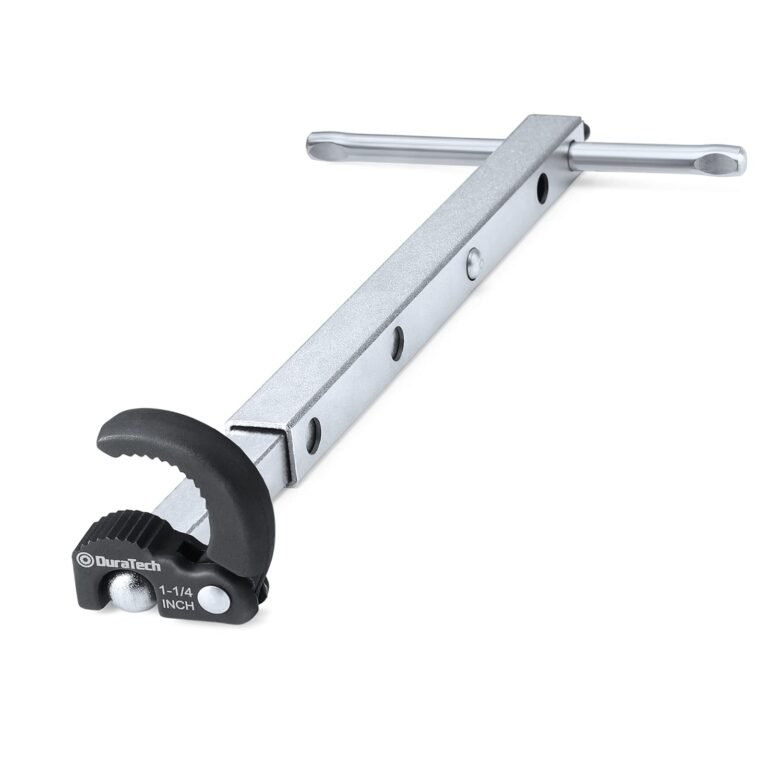
Compare basin wrench vs sink wrench to find the right tool for tight plumbing spaces. Clear pros, cons, and expert tips to help you choose and save time.
Tool Theft Prevention Identification and Asset Management starts with clear IDs, secure storage, smart tracking, and a reliable plan to recover missing tools.