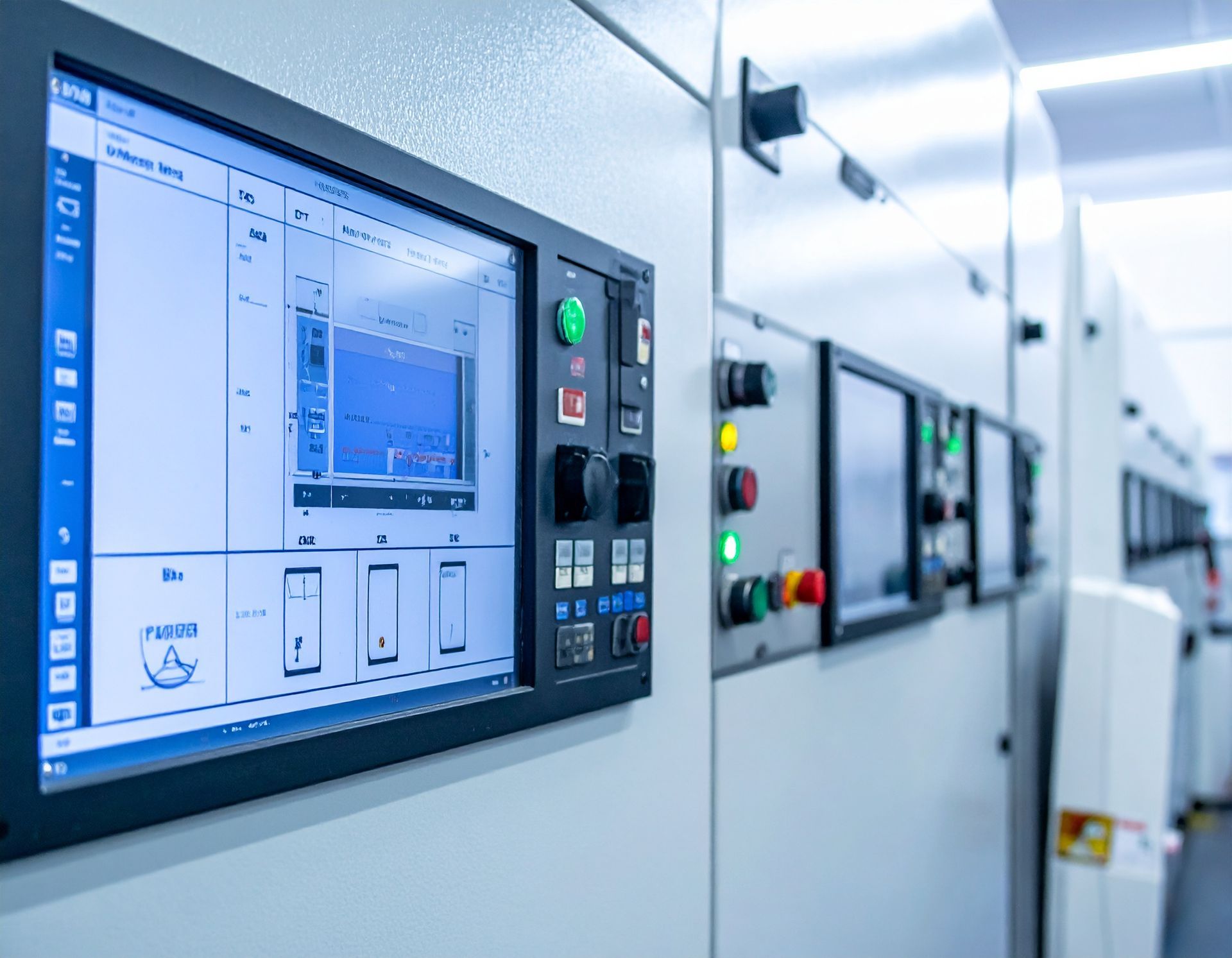
Tool automation uses programmable functions, electronic controls, sensors, and software to make tools perform tasks with greater control and repeatability. Smart controls help users adjust settings, manage tool behavior, monitor performance, and reduce unnecessary manual work.
Across the United States, professional workshops, construction crews, repair shops, and manufacturing plants use many types of powered tools. Some tools have basic electronic speed controls. Others offer custom settings, sensors, and wireless connections. Larger machines may use programmable logic controllers to manage complete work cycles. These systems help workers control how equipment starts, runs, and stops.
Tool automation is not limited to large factories. A cordless drill with adjustable torque settings is one simple example. A production machine that reads sensors and changes its operation is a more advanced example. Both use control systems to guide tool behavior. The main difference is the level of automation and the work each system can perform.
Smart controls can save time and help reduce mistakes when users set them up well. However, adding more electronics does not always improve a tool. The right system must match the material, task, operator, and work environment. A useful setup also needs clear limits, proper testing, and regular checks.
Source: empoweredautomation.com
What Is Tool Automation and How Do Programmable Functions Work?
Tool automation means using electronic or mechanical systems to control how equipment performs a task. The system may adjust motor speed, limit torque, control movement, or follow a set work cycle. Some functions run on their own after the operator starts the tool. Others need input from a person or another machine.
A programmable function is an operating rule that a user or technician can set. For example, a drill may offer several speed and torque modes. An industrial machine may use a stored program to control a motor, valve, and feed system. Both systems follow instructions, but their size and purpose are different.
Smart controls add more ways to monitor and adjust tool behavior. They may use sensors, a small computer, an app, or a control panel. The system can respond to changing conditions when its design supports that function. This helps the tool work within set limits instead of relying only on manual input.
The simplest way to understand the process is to think of a smart control as a skilled assistant. It receives information, follows rules, and helps guide the tool. It does not know every detail of the job. The operator must still choose the right settings and check the result.
Automation
Equipment performs one or more actions through preset rules, electronic commands, or automatic feedback.
Programmable functions
Users can set operating values or select stored modes for different tasks and materials.
Smart controls
Electronic systems use information from sensors, switches, and software to guide tool operation.
Feedback control
The system checks its output or operating condition and makes an adjustment when the programmed rules allow it.
Connected tools
Compatible tools can share selected information with phones, computers, or equipment management systems.
Programmable Controls Versus Manual Controls
A manual control depends on direct action from the operator. The user turns a dial, presses a button, or changes a mechanical setting. The tool then responds to that input. This method is simple and often works well for tasks that change from one job to another.
A programmable control stores a setting or operating sequence. The user can select it again without making every adjustment from the start. This can help when a shop repeats the same operation many times. It also helps different workers follow the same approved setup.
Neither method is always better. Manual controls may cost less and be easier to repair. Programmable controls may offer better repeatability on work with clear and stable requirements.
Manual control
Best for simple tools, flexible tasks, and work that needs frequent direct adjustment.
Programmable control
Useful for repeat jobs, stored operating modes, and tasks with defined limits.
The Role of a Programmable Logic Controller
A programmable logic controller, or PLC, is an industrial computer used to control machinery and processes. It reads signals from devices such as switches and sensors. It then runs programmed logic and sends commands to motors, valves, relays, or other equipment.
A PLC may control a conveyor, cutting machine, packaging system, or automated work cell. Its program can decide when a machine starts, how long it runs, and when it moves to the next step. This makes it useful for jobs that require a fixed sequence of actions.
Common PLC programming methods include ladder logic, structured text, and function block diagrams. The best method depends on the controller, application, and skills of the person maintaining it.
Input modules
Receive signals from sensors, switches, buttons, and other field devices.
Controller
Processes the signals and follows the stored program.
Output modules
Send commands to motors, valves, alarms, and other equipment.
Common Programmable Functions in Modern Tools
Modern tools can include several programmable or electronic functions. The available options depend on the tool type and model. A cordless drill may offer basic speed and torque settings, while an industrial machine may support a much larger control system.
The most useful functions help users control force, speed, timing, and movement. Some features also protect the motor or reduce unwanted tool reactions. Knowing what each function does makes it easier to select the right tool for a job.
Variable speed control
Allows the user to select or adjust motor speed. This helps match the tool to the material, accessory, and task.
Torque control
Sets a torque limit or operating mode on compatible tools. It can help reduce overdriving and damage to fasteners or workpieces.
Soft start
Raises motor speed in a controlled way during startup. This can reduce sudden movement and startup shock.
Constant speed control
Adjusts motor power to help maintain speed when the load changes, within the tool’s operating limits.
Overload protection
Monitors certain electrical or operating conditions and may reduce power or stop the motor when a limit is reached.
Electronic braking
Uses a control system to slow or stop moving parts after the trigger or switch is released. Actual stopping time depends on the tool.
Preset operating modes
Stores selected combinations of speed, power, timing, or other settings for repeat tasks.
Automatic shutoff
Stops an operation when a defined condition or programmed limit is reached.
Sensor-based adjustment
Uses feedback from sensors to change equipment behavior when the system is designed for that response.
Speed and Power Management
Speed control is useful when a task needs a specific operating range. A drill may need a slower setting for large bits. A grinder may need a suitable speed for its approved accessory. A router may use a variable speed setting to suit the cutter and material.
Some electronic controllers also help maintain speed under load. They may increase motor power when resistance rises. However, this does not give the tool unlimited power. Heavy loads can still cause overheating, reduced performance, or a protective shutdown.
Always check the tool manual before changing speed or power settings. The correct range depends on the accessory, material, and machine design.
Lower speed
Can help with controlled starts, certain large accessories, and tasks that need careful handling.
Higher speed
Can suit operations that need faster cutting, drilling, or material removal when the accessory allows it.
Custom Torque and Precision Settings
Torque control is especially useful for fastening work. A drill clutch can limit the force applied to a screw. A controlled-torque impact tool may offer more advanced settings for specific fastening tasks.
However, a preset does not guarantee the final torque of every joint. Fastener size, thread condition, material, lubrication, joint stiffness, and tool condition can all affect the result. Critical fastening work needs a suitable measurement and verification method.
For example, Milwaukee’s published TORQUE-SENSE setup guide describes a training process for certain compatible tools. It uses ten training rundowns and recommends checking output with a calibrated digital torque wrench. This is a model-specific process, not a universal setup rule for all impact tools.
Fastener protection
Suitable torque settings can help reduce stripped threads and damaged workpieces.
Repeat work
Stored settings can help operators use the same approved starting setup.
Output verification
Use the measurement method required by the job or tool maker when torque accuracy matters.
How Smart Tool Controls and Automation Systems Work
A smart control system works by receiving information and using programmed rules to guide equipment. The system may use a sensor, electronic controller, motor driver, and display. Each part has a clear role in the control process.
The process often follows a simple loop. First, a sensor or switch detects a condition. Next, the controller checks the information against its program. It then sends a command to the tool or machine. If feedback is available, the system checks the result and adjusts its output.
A simple drill may use an electronic board to control motor speed. A factory machine may use several sensors and a PLC to manage an entire production sequence. More complex systems can also share data with monitoring software. The basic idea remains the same: information guides action.
Sensors
Detect speed, temperature, position, pressure, current, movement, or another condition.
Control software
Contains the rules that tell the system how to respond to different inputs.
Electronic controller
Processes input data and decides which command to send.
Actuators and motor drivers
Turn control commands into physical movement, motor output, or another action.
Display or interface
Shows settings, warnings, operating modes, and other information to the user.
Communication system
Allows compatible devices to exchange information through supported wired or wireless connections.
Open-Loop and Closed-Loop Control
Open-loop control follows a command without checking the final result. A simple timer-based machine cycle is one example. The machine runs for a set period and then stops. If the load changes, the system may not adjust its behavior.
Closed-loop control uses feedback to check what the machine is doing. A motor controller may read speed and adjust power to keep the motor near a target. This can help maintain more stable operation when the load changes.
Closed-loop control is useful when a task needs a measured result. However, the sensor must work correctly and the control system must be set up well. Poor sensor data can lead to poor decisions.
Open-loop control
Follows preset commands without checking the final output.
Closed-loop control
Uses feedback to compare actual performance with the desired result.
Wireless Controls and Connected Tool Systems
Some modern tools use Bluetooth or other wireless systems to connect with a mobile app. Depending on the model, the app may support custom settings, tool tracking, inventory records, battery information, or security features.
Wireless control can make certain changes easier. A supervisor may prepare approved modes for a compatible tool. A technician may review tool information without opening the equipment. A contractor may also use connected systems to manage tools across several work areas.
Not every connected tool supports every function. Some models offer tracking but no programmable operating settings. Others allow custom modes but have limited tracking features. Check the exact model and current software support before buying or setting up a system.
Bluetooth connection
Can support short-range communication between a compatible tool and a mobile device.
Mobile configuration
May allow users to change supported operating modes and save settings.
Tool tracking
Can help locate compatible equipment and organize asset records.
Remote management
May allow authorized users to review selected tool information or manage supported features.
How to Set Up Programmable Tool Functions Correctly
A good setup begins with the task, not the technology. First, decide what the tool needs to do and what result you want. Then check whether the tool can perform that task with its available controls.
Before starting, read the tool manual and collect the required accessories. Check the power source, work material, and operating limits. If the tool connects to an app, confirm that the model, phone, and software are supported.
Do not change several settings at once during the first test. Adjust one control, test the result, and record what happens. This makes it easier to find the cause if the tool behaves in an unexpected way.
Basic setup requirements
Have the correct tool, approved accessory, manual, compatible power source, test material, and any required measuring device.
Safety preparation
Check guards, switches, workholding, personal protective equipment, and the work area before testing.
Application details
Know the material, fastener, desired result, and operating limits before choosing a preset.
Step 1: Identify the Work Requirement
Write down the task that needs better control. It may involve drilling holes, driving fasteners, cutting stock, grinding a surface, or running a production machine. Be clear about the result you need.
Decide which variable matters most. You may need a speed limit, torque range, timed cycle, position setting, or automatic stop. Avoid adding features that do not solve a real problem.
Define the result
State what a successful operation should look like and how it will be checked.
Set the operating limits
Identify safe and approved speed, force, temperature, or movement limits.
Step 2: Check Tool and Software Compatibility
Read the exact model number and manual. Look for supported functions, firmware needs, app requirements, and accessory limits. Do not assume that two tools from the same product family have the same controls.
If the system uses a mobile app, check its current requirements. Confirm that your phone supports the required connection and that the tool appears on the manufacturer’s compatibility list.
Model support
Confirm that the exact tool model supports the desired programmable function.
Firmware support
Check whether a software update is required and follow the maker’s update process.
Accessory support
Make sure the blade, bit, wheel, socket, or attachment is approved for the tool and selected setting.
Step 3: Record the Current Settings
Before changing anything, record the current mode and operating values. Take a note of the material, accessory, and work conditions. This creates a useful starting point.
If the tool already has stored presets, check what each one does. Avoid overwriting a working setting until you understand its purpose.
Save a baseline
Record the original settings so you can return to them if the new setup fails.
Note the conditions
Include material type, accessory, load, and other factors that may affect the result.
Step 4: Program the Required Function
Use the tool’s approved controls or configuration app to select the required setting. Change only the values that relate to the task. Follow the instructions for saving the new mode to the tool.
For a PLC-controlled machine, a qualified person should review the control logic, input conditions, output actions, and safety functions. Test changes in the approved commissioning process before returning the machine to production.
Choose the correct mode
Select a preset that matches the application or create a new one when the tool supports it.
Set clear limits
Use values supported by the tool manual and the work specification.
Save and label
Give the setting a clear name so operators can identify its purpose.
Step 5: Test on a Safe Sample
Use scrap material or an approved test piece before starting important work. Keep the workpiece secure and use the correct protective equipment. Watch for unusual noise, vibration, heat, or movement.
Check whether the tool performs the task as expected. If the result is poor, stop and review the setup. Do not keep increasing power or force to hide a problem.
Check the result
Inspect the cut, hole, finish, fastener, or machine output against the work requirement.
Watch tool behavior
Look for unexpected stops, excessive heat, unusual vibration, or unstable operation.
Step 6: Verify and Approve the Setting
Use a suitable measuring tool when the result needs to meet a defined value. For critical torque work, follow the required verification method. For speed or position control, use an appropriate measurement or machine check.
A successful test does not prove that one setting works for every material or fastener. Approve the mode only for the conditions that have been checked. Record any limits that operators need to know.
Measure performance
Compare the actual result with the required value or quality standard.
Document approval
Record the approved tool, setting, material, accessory, and test conditions.
Step 7: Train Users and Monitor Results
Show operators how to select the correct mode and recognize warning signals. Explain which settings they may change and which require approval. Keep the instructions close to the tool or in an accessible work procedure.
Review performance after the tool enters normal use. If the material, accessory, or work method changes, check whether the old setting remains suitable. Update the approved instructions when needed.
Train operators
Explain the purpose of each approved mode and the limits of the control system.
Track performance
Watch for quality changes, repeated shutdowns, setup errors, and unexpected downtime.
Review settings
Recheck stored modes after repairs, firmware changes, or major application changes.
Practical Applications of Smart Tool Controls
Smart tool controls can help in many work settings. The most useful applications are those where a task repeats or where an operating limit matters. The right control can reduce repeated adjustments and make work easier to monitor.
A small workshop may only need a few preset tool modes. A busy production plant may need sensors, PLCs, and connected control software. The investment should match the size of the problem.
Woodworking shops
Variable speed routers, electronic motor controls, and automated dust collection can help manage repeat tasks and machine operation.
Automotive repair
Programmable impact tools and controlled fastening systems can support repeat work when their output is properly verified.
Construction sites
Connected tools can support inventory management, approved settings, and selected security features on compatible equipment.
Metal fabrication
Electronic speed control and automated cutting equipment can help maintain suitable operating conditions.
Manufacturing plants
PLCs and sensors can coordinate machine cycles, conveyors, material handling, and production equipment.
Maintenance departments
Connected equipment records can help teams review tool status, service needs, and asset assignments.
Example: Programmable Controls in a Woodworking Shop
Consider a shop that uses a router for several repeat jobs. The operator may need different speeds for different approved bits and materials. A variable speed control allows the user to select a suitable setting before each task.
If the router has electronic speed control, it may help maintain speed as the cutting load changes. A stored setup record can also remind workers which bit and speed range were approved for a specific job.
The operator must still check the bit, workpiece, feed direction, and machine limits. Electronic control does not prevent every mistake. It works best as one part of a clear work process.
Problem
Workers spend time changing settings and may use inconsistent speed selections.
Control method
Use suitable speed settings and clear setup instructions for each approved application.
Expected benefit
A more repeatable starting setup and less time spent making repeated manual adjustments.
Example: Smart Controls in a Manufacturing Line
Imagine a production line that moves parts through several stations. A sensor detects when a part reaches a work position. A PLC checks the signal and allows the next operation to begin when the required conditions are met.
The controller may then activate a motor, start a machine cycle, and wait for a completion signal. If a required input does not arrive, the programmed system may stop the sequence or report a fault.
This type of setup can help coordinate repeat operations. However, it needs proper engineering, testing, maintenance, and safety design. The control program must match the actual machine and work process.
Input
A sensor detects the part and sends a signal to the controller.
Decision
The PLC checks the signal and the programmed conditions.
Action
The controller sends a command to the machine or conveyor.
Feedback
A sensor or machine signal confirms the next step or reports a problem.
How to Choose the Right Programmable Control System
Choose a control system based on the task, not the number of available features. A simple electronic speed dial may be enough for a small workshop. A connected tool may be useful when custom settings or asset records matter. A PLC is more suitable when several machine actions need to work together.
Before making a purchase, compare the functions that directly affect your work. Check compatibility, setup effort, repair support, and the cost of ongoing software or accessories. A control system should be easy enough for the people who will use and maintain it.
Define the main problem
Identify whether the need is better speed control, torque control, repeatability, tracking, automatic sequencing, or process monitoring.
Check compatibility
Confirm that the tool, controller, accessories, app, and other equipment work together.
Review usability
Make sure operators can understand the controls and select the right settings.
Check maintenance needs
Review firmware support, replacement parts, calibration needs, and service access.
Compare total cost
Include software, training, accessories, repairs, and future replacement costs.
Compare Common Levels of Tool Automation
The following comparison shows how different control levels fit different work needs. These are general categories, not fixed product specifications. Actual features depend on the equipment and manufacturer.
Basic electronic controls
Offer functions such as variable speed, soft start, and overload protection. They suit users who need simple control without complex setup.
Programmable power tools
Offer stored modes and adjustable operating settings. They suit repeat tasks and work that needs consistent starting conditions.
Connected smart tools
Add supported wireless configuration, tracking, and tool information. They suit crews that need better equipment management.
PLC-based machine controls
Coordinate sensors, motors, and machine sequences. They suit workshops and plants with repeat automated processes.
Integrated automation systems
Connect machine controls with monitoring and production software. They suit larger operations with several related work processes.
Questions to Ask Before Buying
Ask the manufacturer which functions are available on the exact model. A product family may contain tools with different control features. Check the manual and current support documents rather than relying on a general product description.
Also ask what happens when the wireless connection fails or the app is unavailable. Find out whether the tool keeps its saved settings and whether the operator can still use its normal controls. These details can affect daily work.
Can I save custom modes?
Check the number of modes, storage method, and whether settings remain on the tool.
Can I control the tool without an app?
Check the available physical controls and the behavior during connection loss.
Are the settings verified?
Find out what measurement, calibration, or testing method the application requires.
Will the system remain supported?
Review software updates, device compatibility, service options, and support terms.
Can the system grow?
For industrial equipment, check whether the controller can support future sensors, inputs, outputs, and communication needs.
Safety, Security, and Limitations of Smart Tool Controls
Smart controls can improve process control, but they do not make dangerous equipment safe by themselves. A programmed limit may reduce certain risks, yet sensors and electronic parts can fail. Operators must continue to use the required guards, safe work methods, and protective equipment.
In the United States, OSHA’s machine guarding requirements under 29 CFR 1910.212 address hazards from moving parts and points of operation. Its control of hazardous energy rule, 29 CFR 1910.147, covers applicable servicing and maintenance work. Employers must follow the standards that apply to their machines and workplaces.
A normal stop command is not the same as energy isolation. A machine can retain stored electrical, mechanical, pneumatic, hydraulic, or other energy after it stops. Follow the approved lockout/tagout procedure when servicing or maintaining equipment that requires energy control.
Cybersecurity also matters when tools connect to networks or mobile devices. Unauthorized access may affect stored settings or equipment information. A company should manage user access and keep its connected systems under proper IT and operational technology controls.
Keep physical guards in place
Do not remove or bypass guards because a tool has electronic protection or an automatic stop feature.
Understand emergency stops
Know how the machine stops and what hazards may remain after the stop command.
Use proper energy isolation
Follow applicable lockout/tagout procedures before covered servicing and maintenance tasks.
Control access
Use authorized accounts and suitable access permissions for connected tool systems.
Protect stored data
Review how the software stores tool records, location data, operating history, and user information.
Update carefully
Use approved firmware and software updates, and verify the tool after changes.
Why Electronic Protection Is Not a Safety Guarantee
A sensor may fail to detect a condition. A control board may stop working. A machine may also have a mechanical fault that its software cannot detect. These are reasons to keep required physical safeguards and inspection routines in place.
Some presence-sensing systems are suitable only for machines that can stop before a worker reaches the danger area. Their design must account for stopping time, sensor placement, and machine movement. A qualified machine safety professional should review these systems before use.
Never treat a general-purpose smart feature as a safety-rated function unless the exact system has been designed and validated for that role.
Sensor limits
A sensor only detects the conditions it was designed to measure.
Mechanical limits
Electronic controls cannot prevent every mechanical failure or unexpected movement.
Operator responsibility
Workers still need training and must follow approved operating and maintenance procedures.
Wireless Connectivity and Data Risks
Connected tools may store equipment IDs, usage details, location information, and custom settings. These records can help a business manage its equipment, but they also need clear access rules. Decide who can view, change, or delete the information.
Use strong account security and enable extra login protection when the service offers it. Avoid sharing one account across an entire crew when individual access is available. Remove access when a worker no longer needs it.
For industrial control systems, network changes should be handled by people who understand both machine operation and cybersecurity. Avoid exposing machine controllers directly to public networks. Keep approved backup copies of control programs and settings.
Account protection
Use individual accounts and strong authentication where supported.
Data access
Limit access to tool settings and equipment records based on work roles.
Backup planning
Keep approved copies of important programs and configuration records.
Common Smart Control Problems and How to Troubleshoot Them
When a programmable tool behaves poorly, start with the simplest checks. Review the selected mode, power source, accessory, and connection before assuming the controller has failed. Stop using the equipment if it shows signs of overheating, electrical damage, or unsafe movement.
Do not open electronic parts or bypass a protective function to keep the tool running. Follow the manual and refer repairs to an authorized service provider when the fault involves internal electrical or control components.
The tool will not connect
Check Bluetooth or network settings, app permissions, battery level, device compatibility, and whether the tool is within connection range.
Custom settings do not save
Confirm that the selected model supports custom modes and follow the correct save or synchronization process.
The tool stops under load
Check the accessory, material, load, ventilation, battery condition, and any overload or temperature warning.
Speed changes unexpectedly
Review the selected mode, trigger input, load conditions, and any active electronic control feature.
The tool gives inconsistent results
Check the work material, accessory wear, setup, measurement method, and whether the stored setting fits the application.
The machine will not start
Check the approved start conditions, guard interlocks, emergency stop status, and displayed fault information.
A Safe Troubleshooting Sequence
First, stop the work and place the equipment in a safe condition. Read any warning or fault message. Check the user manual for the meaning of the code and the approved response.
Next, inspect external items that can be checked safely. These may include the battery, power supply, accessory, cable, selected mode, and connection status. Do not reach into moving parts or remove covers while equipment is energized.
If the problem remains, record the model number, fault code, operating condition, and recent changes. This information can help a technician find the cause. Use an authorized service provider when internal repairs or control-system changes are needed.
Success sign
The tool starts and operates within its approved limits, and the test result meets the work requirement.
Failure sign
The tool continues to shut down, displays repeated faults, behaves unpredictably, or fails a required quality check.
Next action
Stop operation and arrange qualified inspection when the cause cannot be found through approved user checks.
Measuring the Productivity Benefits of Tool Automation
A smart control system should produce a useful result that can be measured. Faster work is one possible benefit, but it is not the only one. Better repeatability, fewer setup errors, reduced rework, and clearer equipment records may also matter.
Start by recording performance before making a change. Measure setup time, cycle time, defects, tool downtime, and the number of completed tasks. Then collect the same data after the new control system has been used for a suitable period.
Use similar work conditions when comparing results. A change in material, operator, accessory, or job size can affect the outcome. Without a fair comparison, it is difficult to know whether automation caused the improvement.
Cycle time
Measure how long the tool or machine takes to complete one defined task.
Setup time
Record the time needed to prepare and select the correct operating settings.
First-pass quality
Track how often work meets the required standard without rework.
Downtime
Record time lost to faults, repairs, connection problems, and unexpected stops.
Operator consistency
Check whether different trained users can achieve similar results with the approved setup.
Maintenance cost
Track repairs, replacement parts, calibration, software, and support costs.
A Simple Productivity Calculation
Consider a hypothetical shop that completes 80 repeat tasks each day. Before automation, each task takes 45 seconds. After a tested control change, each task takes 40 seconds under similar conditions.
The difference is 5 seconds per task. Across 80 tasks, the total time saved is 400 seconds, or about 6 minutes and 40 seconds per day. This is a simple estimate, not a promise of actual savings.
The shop should also check quality and downtime. If the new setting causes more defects or requires extra maintenance, the time saving may not be worthwhile. A useful decision considers the full process.
Original time
80 tasks multiplied by 45 seconds equals 3,600 seconds.
New time
80 tasks multiplied by 40 seconds equals 3,200 seconds.
Estimated time difference
3,600 seconds minus 3,200 seconds equals 400 seconds, or 6 minutes and 40 seconds.
Build a Long-Term Improvement Plan
Review the results after the system has been in normal use. Look for repeated faults, poor settings, and training gaps. Ask operators which controls help and which ones make the work harder.
Keep a record of approved settings and changes. This helps the shop maintain consistent work when tools are repaired or replaced. It also gives future technicians a clear starting point.
Review data
Compare actual performance with the original baseline.
Fix weak points
Address poor settings, worn accessories, training issues, and recurring faults.
Update procedures
Keep approved tool modes and operating instructions current.
Maintenance and Management of Programmable Tool Systems
Programmable tools need regular care just like manual equipment. Electronic controls do not remove the need to inspect motors, batteries, switches, accessories, cables, and mechanical parts. A damaged tool may give poor results even when its settings are correct.
Create a maintenance plan based on the tool manual and the amount of work it performs. Some equipment needs routine cleaning and inspection. Other systems may also need calibration, software updates, backup checks, or sensor testing.
Keep a service record for each important tool or machine. Include its model, serial number, approved settings, repair history, and firmware details when relevant. These records can help identify repeated faults and plan future replacement.
Clean and inspect
Remove dust and debris using the approved method. Check vents, switches, cables, guards, and moving parts.
Check batteries and power
Use approved power sources and inspect batteries, chargers, and connections for damage.
Review software
Check for supported updates and follow the manufacturer’s installation instructions.
Verify sensors
Check sensor operation and calibration where the system requires it.
Back up programs
Store approved copies of machine programs and important configuration settings.
Train maintenance staff
Make sure technicians understand the tool’s electronic functions and service limits.
When to Call a Qualified Technician
Some problems need more than basic cleaning or a settings check. Internal circuit faults, damaged sensors, failed control boards, and unexpected machine movement require proper inspection. Industrial control changes may also need a qualified automation technician or engineer.
Get professional help when a tool repeatedly shuts down without a clear cause, loses important settings, or behaves differently after a repair. For machine safety systems, use qualified personnel who can review the full safeguarding design and applicable requirements.
Do not bypass an interlock or change safety-related logic to restore production. A short delay for proper repair is better than operating equipment with an unknown safety condition.
Electrical faults
Seek qualified service for damaged wiring, burning smells, exposed conductors, or repeated electrical faults.
Control system faults
Use trained technicians for controller errors, sensor failures, and unexplained machine actions.
Safety system changes
Have qualified professionals assess and validate changes to guards, interlocks, and safety controls.
Next Questions to Resolve Before Adopting Smart Controls
Choosing an automation system raises questions that go beyond the feature list. The most useful next questions concern compatibility, accuracy, connection loss, and long-term support. These points can affect whether a control system works well in daily use.
A review of official controller information, manufacturer support material, connected-tool documentation, and OSHA guidance shows that the details are often model-specific. General automation guides explain the basic control process, but individual product documents are needed to confirm supported features and setup steps.
The following gap map separates questions found in the reviewed product support material from practical questions inferred from the deployment process. It helps readers identify what they should verify before committing to a system.
Question: Which tool models support programmable settings?
Basis: Observed in manufacturer compatibility and feature documentation. Coverage: Shallow in general automation guides. Reader benefit: Check the exact model, supported functions, and software version before purchase. Priority: High.
Basis: Observed in controlled-torque setup instructions. Coverage: Shallow in basic tool descriptions. Reader benefit: Understand the need for application-specific testing and suitable torque verification. Priority: High.
Question: What happens when wireless connectivity is lost?
Basis: Inferred next need from connected-tool setup requirements. Coverage: Not fully checked across all models. Reader benefit: Confirm whether saved modes remain available and whether normal physical controls still work. Priority: High.
Question: Can smart controls replace physical machine guards?
Basis: Inferred next need from the safety and automation task. Coverage: Answered by OSHA machine guarding guidance. Reader benefit: Avoid treating general electronic features as a substitute for required safeguards. Priority: Critical.
Question: How should a business measure the value of automation?
Basis: Inferred next need from implementation and operating costs. Coverage: Shallow in product feature pages. Reader benefit: Compare setup time, cycle time, quality, downtime, and maintenance cost. Priority: Medium.
Question: Who should maintain the control program?
Basis: Inferred next need from long-term equipment management. Coverage: Not checked across every controller platform. Reader benefit: Assign responsibility for backups, updates, testing, and approved changes. Priority: Medium.
Frequently Asked Questions
Q
What are programmable functions in power tools?
Programmable functions are settings that control how a power tool operates. They may include speed, torque, power, timing, and automatic shutoff. Some tools also allow users to save custom modes for repeat tasks.
The available functions depend on the exact tool model. Always check its manual before changing settings.
Q
What is the difference between smart controls and automation?
Smart controls help monitor or adjust equipment behavior. Automation uses programmed actions to perform part or all of a task with less direct input from the operator.
The two often work together. For example, a sensor may send information to a controller, which then changes a motor setting or starts the next machine step.
Q
Can I program a power tool using my phone?
Some connected power tools support mobile configuration through a compatible app. Depending on the model, users may be able to save operating modes, change supported settings, or review tool information.
Not every Bluetooth tool supports programmable functions. Check the model’s feature list, app requirements, and connection instructions before trying to configure it.
Q
Do programmable tool controls improve accuracy?
They can improve repeatability by helping users apply the same approved starting settings. Electronic speed control, preset modes, and suitable feedback systems can reduce some forms of manual variation.
However, a preset does not guarantee a perfect result. Material changes, worn accessories, incorrect setup, and measurement errors can still affect accuracy. Important results should be checked with a suitable measurement method.
Q
Are programmable tool systems difficult to maintain?
Basic electronic tool controls may need little extra work beyond normal tool maintenance. Connected tools may also need app support, software updates, and account management.
PLC-based systems require more planning. Their maintenance may include sensor checks, program backups, control testing, and qualified technical support. The work depends on system size and complexity.
Q
Can smart controls make industrial machines safer?
Some properly designed control and sensing systems can help reduce exposure to certain machine hazards. Examples include suitable interlocks and presence-sensing devices.
However, a general smart feature does not automatically provide a safety-rated function. Machines still need the guards and protective measures required for their hazards. Qualified personnel should review safety-related control systems.
✦ Wrapping Up
Conclusion
Tool automation, programmable functions, and smart controls give users more ways to manage equipment. They can control speed, torque, timing, movement, and other operating conditions. They can also support better tool tracking and more organized work.
The best results come from matching the control system to a clear task. Start with the work requirement, check compatibility, choose suitable settings, and test the result. Keep records so other operators can use the approved setup.
Remember that automation is only one part of good tool management. Proper training, maintenance, measurement, and machine safeguards still matter. A simple system that works well is often more useful than a complex system that adds cost without solving a real problem.
💡 Key Takeaway
Choose one repeat task in your workshop or jobsite that needs better control. Record its current setup time, operating settings, and result quality. Then identify one suitable programmable function, verify tool compatibility, test it under controlled conditions, and compare the results before expanding automation to other tools.
Tool Technology Evolution Design Trends and Modern Mechanisms explained. Learn how motors, batteries, sensors, smart controls, and safety shape modern tools.