Tool load management means matching the force, speed, pressure, cutting depth, and operating time to a tool’s rated capacity. Use the correct accessory, secure the workpiece, maintain steady feed pressure, and stop when the tool shows signs of overload. These steps help prevent mechanical damage, unexpected tool failure, and operator injuries.
In American workshops, home garages, construction sites, and manufacturing plants, power tools handle many types of work. Drills bore holes, saws cut lumber, grinders remove material, and machine tools shape metal. Each operation places forces on the tool, its moving parts, and the workpiece. Problems start when these forces exceed what the equipment can safely handle.
Tool load management is the process of keeping those forces within safe working limits. It involves more than choosing a powerful motor. The operator must also consider cutting depth, feed pressure, accessory size, material hardness, workpiece support, and operating time. A small mistake in one area can increase stress across the entire tool.
Mechanical overstress can damage bearings, gears, shafts, motors, cutting edges, and other parts. It can also cause binding, sudden movement, overheating, and loss of control. Good load control helps prevent these problems before they become costly repairs or serious accidents.
There is no single feed rate or pressure setting that works for every tool. A drill cutting soft wood needs a different load from a drill boring hard steel. A saw cutting thin stock also faces different demands from one cutting thick hardwood. The safest approach is to follow the exact tool manual and adjust the work method to the material and operation.
What Is Tool Load Management?
Tool load management is the control of the forces and energy that act on a tool during work. These forces may come from cutting, drilling, grinding, fastening, pressing, or lifting. The tool must handle them without exceeding its design limits.
A tool has several working limits. These may include maximum torque, cutting capacity, operating pressure, spindle speed, feed force, and duty cycle. The exact limits depend on the tool design and the task. The owner’s manual and machine nameplate provide the main reference points.
Mechanical overstress occurs when a part experiences more force or stress than it can safely handle. A single heavy impact can cause immediate damage. Repeated smaller loads can also cause fatigue, loosen joints, wear bearings, or create cracks over time.
The difference between normal load and excessive load is important. A tool needs resistance to perform useful work. However, resistance should remain within its intended operating range. The goal is not to remove the load but to control it.
Working load
The force, torque, pressure, or resistance that a tool faces during normal operation.
Rated capacity
The operating limit or approved capacity stated by the manufacturer for a specific tool or machine.
Mechanical overstress
Excessive stress that can damage or weaken a mechanical part.
Duty cycle
The permitted pattern of operation and rest for equipment that needs time to cool.
Reaction torque
The force that acts back on the operator when a powered tool applies rotational force.
Why Excessive Load Causes Mechanical Damage
Every mechanical part has a limit. A shaft can bend under excessive force. A gear can lose teeth under heavy impact. A bearing can wear faster when it carries more load than intended. A motor can overheat when it works too hard for too long.
Heat and vibration can make the problem worse. Excessive friction creates heat, while loose or unbalanced parts create vibration. These conditions may increase wear and reduce the life of nearby components.
The operator may also face extra physical stress. A drill that binds can twist suddenly. A heavy grinder can become harder to control when the workpiece catches. Load management must therefore protect both the equipment and the person using it.
What Factors Increase Tool Load?
Several conditions affect the load placed on a tool. These conditions often work together. A dull cutting edge, excessive feed pressure, and poor workpiece support can create much more resistance than any one factor alone.
Understanding these factors helps operators find the cause of overload instead of simply applying more force. The same tool may work well in one setup and struggle in another because the material, accessory, or cutting method has changed.
Material hardness
Hard wood, thick metal, dense plastic, and abrasive materials can create greater cutting resistance. Match the tool and accessory to the material.
Feed pressure
Pushing too hard can slow the tool, increase heat, bend accessories, and create sudden binding.
Cutting depth
A deep cut removes more material at once. This can increase resistance and place greater stress on the motor and cutting parts.
Tool condition
Dull blades, damaged bits, worn bearings, and loose components can increase friction and vibration.
Accessory selection
An oversized, unsuitable, damaged, or incorrectly rated accessory can place extra stress on the tool.
Operating speed
The wrong speed can increase heat, reduce cutting quality, or create unsafe conditions. Use the speed range specified for the tool and accessory.
Workpiece stability
Loose or poorly supported material can twist, move, or pinch the cutting accessory.
Operating duration
Long periods of heavy work can raise motor and component temperatures beyond the permitted operating range.
The Effect of Feed Pressure and Cutting Resistance
Feed pressure is the force used to move a tool or workpiece through an operation. The correct amount depends on the material, tool design, and cutting accessory. Too much pressure can overload the machine.
For example, pushing a drill too hard into dense material may slow the motor and increase the chance of a sudden bind. A saw may also struggle when the operator forces it through a thick board. A steady feed lets the cutting edge remove material without unnecessary strain.
A sharp cutting edge usually needs less force than a dull one. This is why sharpening and timely replacement are important parts of load management. Increasing hand pressure is not a proper fix for a worn cutting accessory.
Use steady pressure
Apply only the force needed to maintain the intended cutting action.
Watch tool speed
A sudden loss of speed may indicate excessive resistance or an unsuitable setup.
Reduce the load
If the tool struggles, review the accessory, cutting depth, material, and feed method.
How Workpiece Support Changes Mechanical Load
Workpiece support affects how forces move through the tool and material. A loose board can shift during a cut. A poorly supported metal part can vibrate or bend. Both conditions may cause the accessory to bind.
Use suitable clamps, vises, fixtures, fences, and supports. Large sheets need support across their span. Small pieces should not be held by hand during powered drilling when they can be secured safely.
Stable workholding reduces unexpected movement. It also allows the operator to use a more natural grip and maintain better control.
How to Set the Correct Tool Load Before Operation
A good load plan begins before the motor starts. Check the task, material, tool capacity, accessory, and workpiece support. This short review can prevent many common overload problems.
Do not guess at maximum pressure, speed, or cutting depth. Use the manufacturer’s instructions for the exact model and accessory. Different tools can have very different limits, even when they look similar.
Step 1: Identify the operation
Decide whether the task involves drilling, cutting, grinding, fastening, shaping, or another process. Each operation creates a different type of load.
Step 2: Check the rated capacity
Read the tool manual and nameplate. Check maximum workpiece size, torque, pressure, speed, cutting depth, and duty-cycle limits where applicable.
Step 3: Select the correct accessory
Choose a bit, blade, wheel, cutter, or socket that is approved for the tool and the material. Check its size, condition, and speed rating.
Step 4: Inspect the equipment
Look for cracks, loose fasteners, damaged cords, worn bearings, blocked vents, and other signs of damage. Do not use defective equipment.
Step 5: Secure the workpiece
Use a suitable clamp, vise, fixture, or machine support. Check that the material cannot move into an unsafe position.
Step 6: Set the operating conditions
Choose the approved speed, feed, depth, and pressure for the material and operation. Follow the manual rather than using a universal setting.
Step 7: Check the work area
Make sure the work area is clear, guards are in place, and the operator has stable footing and enough room to control the tool.
Use a Test Operation When Appropriate
A test operation can help reveal problems before a full production run. When the task and machine allow it, use a suitable scrap piece or test material. Check the cut, hole, finish, vibration, and tool response.
The test must follow the same safety rules as the main operation. Keep guards in place and use the proper workholding method. Never test an unfamiliar machine by deliberately pushing it toward an overload.
If the tool struggles during the test, stop and review the setup. A smaller cutting depth, a suitable accessory, or better support may be needed. If the cause is unclear, consult the manual or a qualified technician.
How to Manage Load During Tool Operation
During operation, maintain a steady feed and watch how the tool responds. Do not use extra force to make up for poor cutting performance. A tool should perform its intended task without repeated stalling, severe vibration, or unusual heating.
Keep the tool aligned with the work. Avoid unnecessary side pressure, twisting, and sudden changes in feed. These actions can create forces that the tool or accessory was not designed to handle.
Managing Load When Using Power Drills
Drills experience rotational torque and forward feed pressure. Both can increase when a bit enters hard material or becomes trapped. Select a bit that matches the drill’s capacity and the material being drilled.
Keep the bit properly seated in the chuck. Use the auxiliary handle for work that creates strong reaction torque. Clamp small workpieces instead of holding them by hand.
Apply even pressure and reduce the feed near the end of a hole. This helps prevent sudden breakthrough and damage to the bit. For large holes, a suitable pilot hole may reduce the effort required.
If a drill stalls, release the trigger at once. Do not keep pressing the trigger in an attempt to force the bit through. Remove the tool from service if damage is suspected, and identify the cause before continuing.
Correct bit size
Stay within the manufacturer’s recommended drilling capacity.
Reaction torque control
Use the second handle or an approved torque-control feature when required.
Jammed bit
Stop the drill and isolate its power before freeing a jammed accessory.
Managing Load on Saws and Cutting Machines
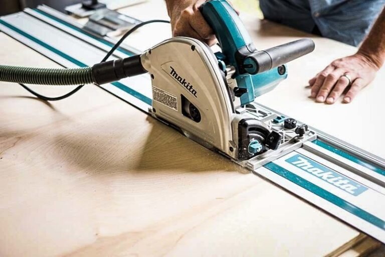
Saws need a suitable blade, stable workpiece support, and controlled feed. A dull or damaged blade can increase resistance and create binding. Use a blade intended for the material and cutting direction.
Feed the material at a steady rate. Do not force it through the blade. If the motor slows or the stock begins to pinch, stop the operation and identify the cause. Never reach near a moving blade to correct the problem.
Large boards and sheets need proper support. Unsupported material may sag and close the cut behind the blade. This can cause binding and kickback. Keep the correct guards, fences, spreaders, and anti-kickback devices in place.
For stationary cutting machines, the feed rate and depth of cut must suit the machine, cutter, and material. Avoid heavy cuts that exceed the machine’s capacity.
Sharp blade
Maintain a clean, sharp, correctly installed blade.
Stable stock
Support long and wide workpieces to prevent sagging and twisting.
Controlled feed
Maintain the approved feed direction and avoid sudden pressure.
Managing Load on Routers and Milling Machines
Routers and milling machines place cutting forces on the spindle, cutter, bearings, and workholding system. A deep cut or heavy feed can increase these forces. Multiple suitable passes may be safer than one excessive cut when the tool manual permits that method.
Check cutter size, shank fit, installation, and maximum permitted speed. An incorrectly mounted or unsuitable cutter can become loose or break. Keep the workpiece secure and make sure clamps remain clear of the tool path.
Cutting speed depends on the material, cutter type, depth, finish, and machine rigidity. A suitable setting for one material may be wrong for another. Use the machine instructions and approved cutting data.
Correct spindle speed
Never exceed the permitted speed of the cutter or tool holder.
Controlled depth
Use an approved depth of cut that the machine can handle.
Secure mounting
Check the cutter, holder, workpiece, and fixture before starting.
Managing Load on Grinders and Abrasive Tools
Grinding creates friction and heat. Excessive pressure can damage the abrasive accessory, increase heat, and reduce control. Use the correct wheel or disc for the material and operation.
Check the accessory’s maximum speed rating against the tool’s operating speed. The accessory must be suitable for the tool and its intended use. Inspect it for cracks, damage, and other defects before installation.
Use the required guard and handle. Do not apply side pressure to an abrasive wheel that is not designed for side grinding. Allow the abrasive surface to work without forcing it into the material.
Accessory rating
The accessory must be approved for the tool and its operating speed.
Light, controlled contact
Use the pressure recommended for the grinding operation.
Heat control
Follow the correct work and cooling procedure for the material and accessory.
Managing Load on Impact and Fastening Tools
Impact drivers and impact wrenches create repeated rotational force. The socket, fastener, drive mechanism, and workpiece must all suit that force. Use impact-rated accessories where the tool requires them.
Keep the socket aligned with the fastener. Poor alignment can damage the socket or fastener and create unnecessary side loading. Avoid continuing to apply impact after the required fastening operation is complete.
When a joint needs a specified final torque, use the approved torque-control process. An impact tool’s advertised maximum torque does not automatically establish the correct final torque for every fastener.
Signs That a Tool Is Under Excessive Load
A tool often gives warning signs before a major failure. Operators should learn the normal sound, movement, temperature, and cutting response of their equipment. A sudden change deserves attention.
One sign alone does not always prove mechanical overload. For example, vibration may come from an unbalanced accessory or loose mounting. However, several warning signs together indicate that the operation should stop for inspection.
Motor speed drops
The motor slows sharply when the accessory enters the material. This may indicate excessive resistance, a dull accessory, or an unsuitable operating setup.
Repeated stalling
The motor stops during normal work. This can indicate overload, binding, or another mechanical or electrical problem.
Unusual vibration
The tool shakes more than normal. Possible causes include a damaged accessory, poor alignment, loose parts, or an unstable workpiece.
Excessive heat
The housing, motor, accessory, or work area becomes unusually hot. Check the manual for temperature and cooling guidance.
Unusual noise
Grinding, knocking, squealing, or sudden changes in motor sound may point to wear, damage, or excessive resistance.
Poor work quality
Rough cuts, inaccurate holes, damaged fasteners, or repeated tool marks may indicate incorrect speed, feed, alignment, or accessory condition.
Repeated protection trips
An overload protector or circuit protection device activates during work. Find the cause instead of repeatedly resetting the equipment.
Loss of operator control
The tool twists, pulls, or becomes difficult to hold. Stop before reaction forces create an injury risk.
What to Check When These Warning Signs Appear
First, release the control and stop the operation. Allow all moving parts to stop. Disconnect the power source before inspecting, adjusting, or removing a jammed accessory.
Check the accessory for wear, damage, incorrect installation, or unsuitable size. Then inspect the workpiece for movement, pinching, or poor support. Review the feed pressure, cutting depth, and operating speed.
If the problem remains, do not keep testing the tool under heavy load. The motor, bearings, gearbox, or internal controls may need professional inspection. Remove defective equipment from service until it is repaired.
Stop immediately
Do not continue work when the tool shows severe vibration, binding, smoke, or loss of control.
Isolate the equipment
Unplug it, remove the battery, or isolate its air or hydraulic supply as appropriate.
Find the cause
Inspect the accessory, workpiece, alignment, and machine condition.
Get qualified help
Use a qualified repair person when internal damage or an unknown fault is suspected.
Understanding Torque, Force, and Mechanical Load
Basic mechanical calculations can help explain why some tool setups create more stress than others. Torque is the turning effect of a force around an axis. It depends on the size of the force and its distance from the axis.
The basic formula is torque equals force multiplied by the perpendicular lever arm. In U.S. customary units, torque is often measured in foot-pounds or inch-pounds.
For example, imagine applying a force of 100 pounds at a perpendicular distance of 1 foot from a rotating point. The resulting torque is 100 foot-pounds. This is a hypothetical calculation, not a recommended tool setting or a safe operating limit.
Torque
Torque = Force × Perpendicular distance from the axis.
Rotational power
Power depends on torque and rotational speed. More torque at the same speed requires more power.
Feed force
Feed force is the push needed to move a cutting or working tool into the material.
Bending load
A force applied away from a support can bend a shaft, handle, or other component.
Why Torque Control Matters
A drill or impact tool produces rotational force. The operator must control the reaction force that acts in the opposite direction. When an accessory binds, the reaction can rise quickly.
This is why an auxiliary handle, torque bar, or suitable reaction-control feature can matter during demanding work. It gives the operator better control over the tool’s movement.
Do not use a simple torque calculation as a substitute for the tool’s rating. Real tools have limits based on gear design, motor capacity, accessory strength, speed, and operating conditions.
Why There Is No Universal Safe Feed Pressure
Feed pressure depends on the tool, material, cutting edge, and operation. A force that works for one drill bit may damage another. The same pressure may also create a different result in wood and metal.
Use the manufacturer’s operating guidance. Watch for signs that the tool is struggling. If it loses speed, binds, or creates unusual vibration, stop and reassess the setup rather than increasing pressure.
Preventing Mechanical Overstress Through Maintenance
Regular maintenance reduces unnecessary mechanical resistance. A clean, sharp, correctly adjusted tool usually performs its task with less effort than a damaged or poorly maintained one.
Maintenance should follow the manufacturer’s schedule. It should also respond to changes in sound, vibration, temperature, and performance. A tool that suddenly needs more force may have a developing fault.
Maintain cutting edges
Sharpen or replace blades, bits, and cutters when needed. Remove damaged accessories from service.
Check moving parts
Inspect bearings, shafts, gears, belts, and other moving components for wear, looseness, or damage.
Follow lubrication instructions
Use the correct lubricant and service interval. Too little or unsuitable lubrication can increase friction and wear.
Keep cooling vents clear
Remove dust and debris using an approved cleaning method. Blocked vents can reduce cooling.
Inspect accessories
Check wheels, blades, sockets, bits, and holders before use. Confirm that they are properly installed.
Check fasteners and guards
Make sure approved guards, handles, mounting points, and safety devices are secure and functional.
Follow service intervals
Replace worn components and arrange professional service when the manual or inspection findings require it.
Heat and Duty Cycle Management
Heat is a major concern during heavy tool use. Motors, batteries, bearings, and gear systems all operate within temperature limits. Long periods of heavy work may raise temperatures beyond those limits.
Check whether the tool has a stated duty cycle or cooling period. Some tools are designed for continuous operation. Others need regular rest periods. Never assume that every tool can run at full load without a break.
If a tool has an overload or thermal protection system, treat it as a protective feature. Do not bypass it or repeatedly reset it without finding the cause. Follow the exact cooling and restart procedure in the manual.
Operator Position and Physical Load
Mechanical load also affects the person holding the tool. Heavy equipment, reaction torque, awkward reaches, and repeated gripping can strain the hands, wrists, arms, shoulders, and back.
Keep the tool close to the body when practical. Maintain a stable stance and a neutral wrist position. Support heavy tools with an approved stand or balancer when the job requires it.
Take suitable breaks during prolonged work. Rotate tasks when practical. Stop if unusual pain, numbness, tingling, or loss of grip occurs. Anti-vibration gloves do not replace proper tool selection, maintenance, and exposure control.
What to Do When a Tool Becomes Overloaded
An overloaded tool should not be forced back into operation. Stop the machine and identify the reason for the excessive load. Restarting without correcting the cause may damage the equipment or expose the operator to another sudden movement.
The correct response depends on the tool’s power source and design. Electrical, battery-powered, pneumatic, and hydraulic tools may require different isolation steps. Follow the manufacturer’s instructions and the site’s safety procedures.
Step 1: Release the control
Release the trigger, switch, or operating control. Do not keep applying power to a stalled tool.
Step 2: Wait for all movement to stop
Keep clear of the accessory until it has fully stopped. Do not assume that a switched-off machine is motionless.
Step 3: Isolate the power
Unplug the tool, remove its battery, or isolate the pneumatic or hydraulic supply. Release stored pressure using the approved procedure.
Step 4: Inspect the setup
Check for a jammed accessory, dull cutting edge, damaged component, poor workpiece support, or incorrect setting.
Step 5: Correct the problem
Replace damaged parts, improve support, select the correct accessory, or adjust the operation according to the manual.
Step 6: Arrange repair if needed
Remove the tool from service if the motor, gearbox, bearing, guard, switch, or other safety-related part may be damaged.
Step 7: Restart only when safe
Follow the manufacturer’s cooling, inspection, and restart instructions before returning the tool to work.
When Professional Inspection Is Necessary
Some overload problems are easy to identify. A dull bit or poorly supported board may be corrected with a proper replacement or setup change. Other problems involve internal mechanical or electrical damage.
A qualified technician should inspect equipment that produces repeated abnormal noise, burning smells, smoke, severe vibration, or unexpected shutdowns. The same applies when a protective device trips repeatedly or a guard no longer works correctly.
Industrial machines may require formal isolation and lockout/tagout procedures before maintenance. Only trained and authorized people should perform work that exposes them to stored electrical, pneumatic, hydraulic, spring, or gravitational energy.
Internal damage
Suspected bearing, gear, motor, shaft, or control damage requires proper inspection.
Failed safety devices
Never operate equipment with a damaged guard, emergency stop, or required protective device.
Unknown repeated faults
Repeated overloads need a proper diagnosis before the equipment returns to service.
Common Tool Load Management Mistakes
Many overload problems come from small decisions made during setup or operation. Operators may try to save time by applying more force, skipping inspection, or using an accessory that is close to the correct size. These shortcuts can increase mechanical stress.
A consistent operating method is more reliable than relying on the operator’s strength or experience alone. The following mistakes deserve particular attention.
Forcing the tool through the material
Extra pressure can slow the motor, increase friction, and cause binding. Correct the feed rate or cutting setup instead.
Using the wrong accessory
An unsuitable bit, blade, wheel, or socket may create excess resistance or fail under load.
Ignoring dull cutting edges
A dull accessory needs more force and may produce extra heat and vibration.
Taking cuts that are too deep
Excessive depth can overload the cutting system. Use an approved depth and feed.
Holding loose material by hand
Unstable stock can move, spin, or become trapped. Use suitable workholding.
Ignoring abnormal noise
Unusual sound may indicate damage, looseness, or excessive resistance. Stop and inspect.
Running equipment beyond its duty cycle
Long periods of heavy operation can create excessive heat and shorten component life.
Repeatedly resetting overload protection
Protection systems are not a substitute for proper load control. Identify and correct the cause.
Removing guards for convenience
Never bypass required machine guards or safety devices to make an operation easier.
Using poor body position
Overreaching and awkward wrist positions reduce control and increase physical strain.
Why More Tool Power Is Not Always the Answer
A larger motor does not automatically solve an overload problem. The accessory, workholding system, gearbox, bearings, and machine frame must also suit the task.
A more powerful tool can still fail when it uses the wrong accessory or cuts beyond its approved capacity. It may also produce stronger reaction forces that are harder to control.
Before changing to a larger machine, review the actual cause of the overload. The correct solution may be a sharper cutter, better support, a different feed rate, or a more suitable accessory.
Building a Reliable Tool Load Management Routine
A repeatable load management routine helps prevent the same problem from returning. It also gives operators a clear way to identify changes in tool performance.
For a home workshop, a short inspection before each job may be enough for simple tools. Busy workshops and industrial sites may need written inspection records, scheduled maintenance, and operator training.
Before work
Review the task, manual, capacity, accessory rating, workpiece condition, and safety devices.
During work
Maintain steady feed, control reaction forces, and watch for speed loss, heat, noise, and vibration.
After work
Switch off and isolate the equipment as required. Clean it using an approved method and inspect for new damage.
During maintenance
Follow the service schedule and replace worn or damaged parts with approved components.
When problems repeat
Record the task, material, accessory, operating conditions, symptoms, and corrective action.
Use Simple Inspection Records
Inspection records can reveal patterns that are hard to notice during individual jobs. For example, repeated overheating may occur only when a certain material or accessory is used.
Record the tool identification, date, inspection findings, operating problem, and corrective action. For production equipment, also record relevant setup and maintenance details.
These records can help a supervisor identify recurring faults, plan service, and provide better operator training. They also support a more consistent approach to equipment care.
Frequently Asked Questions
Q
What is tool load management?
Tool load management is the process of controlling the force, torque, speed, pressure, cutting depth, and operating time placed on a tool. It keeps the equipment within its approved working capacity and helps prevent mechanical damage, overheating, and unsafe movement.
Q
What are the main signs of an overloaded power tool?
Common signs include sudden speed loss, repeated stalling, unusual vibration, excessive heat, strange noises, and poor cutting performance. A burning smell or repeated overload protection trips also require attention. Stop the tool and inspect it before continuing.
Q
How can I prevent mechanical overstress during drilling?
Use the correct drill and bit for the material. Secure the workpiece and use an auxiliary handle when the operation creates strong reaction torque. Apply steady pressure and reduce the feed near breakthrough. Never force a jammed bit.
Q
Does a sharper cutting tool reduce mechanical load?
Yes, a sharp and properly maintained cutting edge generally reduces the force needed to remove material. This can lower resistance, heat, and unnecessary stress on the tool. However, the accessory must still be suitable for the material, speed, and operation.
Q
Can I keep using a tool after its overload protection activates?
Do not immediately resume work. Release the control, isolate the power as directed, and identify why the protection activated. Follow the exact cooling and reset instructions in the owner’s manual. If the problem returns or damage is suspected, remove the tool from service and arrange qualified inspection.
✦ Wrapping Up
Conclusion
Tool load management is essential for reliable equipment operation and safe work. Every tool has limits for force, torque, speed, pressure, and operating time. Staying within those limits helps protect motors, gears, bearings, shafts, accessories, and workpieces.
Good load control starts with the right tool and accessory. It also requires stable workholding, suitable operating settings, steady feed pressure, and regular maintenance. Operators should pay attention to unusual heat, vibration, noise, and speed loss rather than forcing equipment to continue.
When an overload occurs, stop the operation and isolate the equipment before inspecting it. Correct the cause instead of repeatedly restarting the tool. Seek qualified service when damage, repeated faults, or failed safety devices are involved.
💡 Key Takeaway
Before your next job, check the tool’s rated capacity, inspect the accessory, secure the workpiece, and confirm the approved speed and feed settings. During operation, let the tool do the work. Stop immediately if it binds, overheats, vibrates abnormally, or loses speed. Good load management prevents avoidable damage and helps keep every job under control.